My code works, I don’t know why.

國王的耳朵是驢耳朵

使用gdb 靜態分析C 語言名稱和參數相同函數的原始檔位置

| Comments

前言

感謝Scott大大的資訊。

忘記那邊看過的名言:「手上有了新玩具,就會想要馬上拿來用。」

動機

組裝軟體的時候,有一件事很讓我困擾。那就是當整包SDK有兩個以上名稱和參數相同的函數的時候。當這種情況發生時,trace code就很麻煩,你必須要花時間釐清到底最後會使用到那一個函數。而這些config可能用下面兩種方式切換這些名稱和參數相同的函數:

  1. 巨集
    • #if
    • #ifdef
  2. Makefile
    • 在檔案中根據不同變數編譯不同的檔案

我以前會視情況用下面兩種方法找到該函數編譯實際使用的原始檔位置

  1. 下毒藥,只要相同名字的函數都塞入#error 可以辨別的字串。編譯時根據錯誤訊息判斷使用哪個函數
  2. gdb設斷點,runtime透過中斷函數的方式取得函數的檔案和行號

不過Scott大大的今天給的資訊讓我可以更省力的處理這個問題了。

如果只想要知道用法,看完下面指令就可以收工回家了。

1
gdb -ex 'file 你的執行檔或是shared library檔' -ex 'info line 要查的函數' -ex 'quit'

當然用gdb編譯時不要忘記加debug option。

目錄

測試環境

1
2
3
4
5
6
$ lsb_release -a
No LSB modules are available.
Distributor ID:   Ubuntu
Description:  Ubuntu 14.04.5 LTS
Release:  14.04
Codename: trusty

測試檔案

簡單來說,就是實作切換兩種方式同樣名稱和參數的函數:

  1. 巨集
  2. Makefile

所以我們會有

  1. 測試檔案進入點
  2. 測試檔一
    • 實作使用巨集OP1切換同樣名稱和參數
    • 和測試檔二完全一模一樣
  3. 測試檔二
    • 實作使用巨集OP1切換同樣名稱和參數
    • 和測試檔一完全一模一樣
  4. Makefile
    • 除了編譯以外,還提供兩個變數,由command line傳入
      • USE_FILE=1
        • 沒傳入時預設編譯測試檔二,當該參數傳入USE_FILE=1時會變成編譯測試檔一
      • EN_OP1=1
        • 當該參數傳入時才會開啟OP1巨集

test_same_func.c

  • 測試檔案進入點,呼叫func1()。func1()在compile time才被決定
test_same_func.c
1
2
3
4
5
6
7
8
9
10
#include <stdio.h>
extern void func1(void);

int main()
{
    printf("Hello World\n");
    func1();

    return 0;
}

same_func1.c

  • 實作使用巨集OP1切換同樣名稱和參數
  • same_func2完全一模一樣
same_func1.c
1
2
3
4
5
6
7
8
9
10
11
12
13
#include <stdio.h>

#if OP1
void func1(void)
{
    printf("%s: %s_OP1\n", __FILE__, __PRETTY_FUNCTION__);
}
#else
void func1(void)
{
    printf("%s: %s_NOT_OP1\n", __FILE__, __PRETTY_FUNCTION__);
}
#endif

same_func2.c

  • 實作使用巨集OP1切換同樣名稱和參數
  • same_func1完全一模一樣
same_func2.c
1
2
3
4
5
6
7
8
9
10
11
12
13
#include <stdio.h>

#if OP1
void func1(void)
{
    printf("%s: %s_OP1\n", __FILE__, __PRETTY_FUNCTION__);
}
#else
void func1(void)
{
    printf("%s: %s_NOT_OP1\n", __FILE__, __PRETTY_FUNCTION__);
}
#endif

Makefile

提供兩個變數,由command line傳入

  • USE_FILE=1
    • 沒傳入時預設編譯測試檔二,當該參數傳入USE_FILE=1時會變成編譯測試檔一
  • EN_OP1=1
    • 當該參數傳入時才會開啟OP1巨集
1
2
3
4
5
6
7
8
9
10
11
12
13
14
15
16
17
18
19
20
21
22
23
24
25
CFLAGS+=-Wall -Werror -g3
TARGET=test_same_func
SRCS=test_same_func.c

ifeq ($(USE_FILE), 1)
    SRCS += same_func1.c
else
    SRCS += same_func2.c
endif

ifeq ($(EN_OP1), 1)
    CFLAGS += -DOP1=1
endif

OBJS=$(patsubst %.c, %.o, $(SRCS))

$(TARGET): $(OBJS)
  $(CC) -o $@ $^
  gdb -ex 'file $@' -ex 'info line func1' -ex 'quit'

%.o: %.c
  $(CC) $(CFLAGS) -c $^

clean:
  rm *.o *~ $(TARGET) -f

測試結果

前面提過,func1()的實作受兩個變數影響,分別為

  1. 巨集OP1是否有設定
    • 只有OP1 被設定並且非零時才會進入OP1func1()
  2. Makefile變數USE_FILE是否有設定
    • 只有USE_FILE為1的時候才會使用same_func1.c,其他情形都編譯same_func2.c

所以我們make 指令有下面四種變化

  1. 巨集OP1USE_FILE都沒設定
  2. 設定巨集OP1USE_FILE沒設定
  3. 巨集OP1沒設定,但是設定USE_FILE
  4. 全部設定巨集OP1USE_FILE

巨集OP1USE_FILE都沒設定

gdb驗證結果的確是

  1. 編譯same_func2.c
  2. 使用非OP1版本的func1()
1
2
3
4
5
6
7
8
9
10
11
12
13
14
$ make clean
default settings: OP1 disable and use same_func1.c
rm *.o *~ test_same_func -f

$ make
cc -Wall -Werror -g3 -c test_same_func.c
cc -Wall -Werror -g3 -c same_func2.c
cc -o test_same_func test_same_func.o same_func2.o

$ gdb -ex 'file test_same_func' -ex 'info line func1' -ex 'quit'
...
Line 11 of "same_func2.c" starts at address 0x400597 <func1> and ends at 0x40059b <func1+4>.
Hello World
same_func2.c: func1_NOT_OP1

設定巨集OP1USE_FILE沒設定

gdb驗證結果的確是

  1. 編譯same_func2.c
  2. 使用OP1版本的func1()
1
2
3
4
5
6
7
8
9
10
11
12
13
$ make clean
rm *.o *~ test_same_func -f

$ make EN_OP1=1
cc -Wall -Werror -g3 -DOP1=1 -c test_same_func.c
cc -Wall -Werror -g3 -DOP1=1 -c same_func2.c
cc -o test_same_func test_same_func.o same_func2.o

$ gdb -ex 'file test_same_func' -ex 'info line func1' -ex 'quit'
...
Line 5 of "same_func2.c" starts at address 0x400597 <func1> and ends at 0x40059b <func1+4>.
Hello World
same_func2.c: func1_OP1

巨集OP1沒設定,但是設定USE_FILE

gdb驗證結果的確是

  1. 編譯same_func1.c
  2. 使用非OP1版本的func1()
1
2
3
4
5
6
7
8
9
10
11
12
13
$ make clean
rm *.o *~ test_same_func -f

$ make USE_FILE=1
cc -Wall -Werror -g3 -c test_same_func.c
cc -Wall -Werror -g3 -c same_func1.c
cc -o test_same_func test_same_func.o same_func1.o

$ gdb -ex 'file test_same_func' -ex 'info line func1' -ex 'quit'
...
Line 11 of "same_func1.c" starts at address 0x400597 <func1> and ends at 0x40059b <func1+4>.
Hello World
same_func1.c: func1_NOT_OP1

全部設定巨集OP1USE_FILE

gdb驗證結果的確是

  1. 編譯same_func1.c
  2. 使用OP1版本的func1()
1
2
3
4
5
6
7
8
9
10
11
12
13
$ make clean
rm *.o *~ test_same_func -f

$ make EN_OP1=1 USE_FILE=1
cc -Wall -Werror -g3 -DOP1=1 -c test_same_func.c
cc -Wall -Werror -g3 -DOP1=1 -c same_func1.c
cc -o test_same_func test_same_func.o same_func1.o

$ gdb -ex 'file test_same_func' -ex 'info line func1' -ex 'quit'
...
Line 5 of "same_func1.c" starts at address 0x400597 <func1> and ends at 0x40059b <func1+4>.
Hello World
same_func1.c: func1_OP1

延伸資料

(過期) Linux Kernel Pratice 0: Buildroot (2/2) - 自行編譯kernel

| Comments

感謝Scott 大大糾正,選錯平台,這篇使用了ARMv4指令集的測試平台。請大家忽略,正確的版本將會之後更新!

前情提要

上一篇提到,設定實習環境的目標有:

  1. 可以使用ARM 平台。一方面追求流行,一方面我不想再開x86這個副本
  2. 可以方便地建立ARM平台的Linux Rootfs和kernel版本
  3. 可以方便地更改指定要編譯的Kernel版本
  4. 透過Qemu ,使用2的Rootfs和kernel開機
  5. 透過Qemu和搭配的工具可以分析Linux kernel的run time 行為

今天就是來解決3 的項目。更細分的話,這次目標是

  1. 使用官方Linux kernel 編譯Versatile
  2. 編譯出來的kernel binary可以在Qemu上順利載入
  3. 編譯出來的kernel binary可以順利的載入buildroot產生的rootfs,以及網路介面和相關設備

目錄

測試環境

做組裝的最重要的原則之一就是要能夠reproduce,所以交代測試環境是一定要的

1
2
3
4
5
6
7
8
9
$ lsb_release -a
No LSB modules are available.
Distributor ID:   Ubuntu
Description:  Ubuntu 14.04.5 LTS
Release:  14.04
Codename: trusty

$ git --version
git version 2.10.0
  • buildroot 版本
    • commit hash: 14b24726a81b719b35fee70c8ba8be2d682a7313

下載Linux Kernel Source

沒啥好講的,就剪貼指令吧

1
git clone git://git.kernel.org/pub/scm/linux/kernel/git/stable/linux-stable.git

設定和編譯

東西下載完不是就閉著眼睛開幹,因為我們在開始編譯前需要

  1. 切換到你想要研究的版本
  2. 如果不是x86,你需要指定平台
  3. 細項Kernel config設定

那麼就來見招拆招吧

切換版本

非常簡單,先git tag,切過去就好。我要切到4.4.2就是

1
2
3
git tag                 # 找你要的版本
git checkout v4.4.2     # 切到tag
git checkout -b v4.4.2  # 理論上會這邊改東改西,就先開branch吧

設定ARM Versatile預設config

先講結論

1
make ARCH=arm versatile_defconfig

開始沒人要看的解釋吧。基本上也亂看找出來的,簡單講一下當初的「脈絡」

  1. 我知道我們平台是versatile,所以就find | grep versatile。從一堆檔案中我看到有趣的檔案./arch/arm/configs/versatile_defconfig
  2. 接下來就是要找make 的時候怎麼和這個檔案勾起來。網路上找一下會發現一個變數ARCH,剩下就試看看make ARCH=arm versatile_defconfig,能不能動,可以動所以打完收工。

然後你就知道

  1. Linux kernel source中有些平台會提供default config
  2. 透過ARCH可以讓make時自動參考這些檔案產生config

設定Qemu VM支援的硬體

建議不要把buildroot compile cache打開。我花了很多時間在kernel 編譯後Qemu還是沒有使用編譯後的kernel的問題,最後發現關閉buildroot compile cache問題就消失了。

如果閉著眼睛開始編譯,你會很高興地發現可以開機了,但是接下來就會很失望的發現kernel panic,原因是認不出開機的disk。

之所以會發生這樣的原因是因為Linux kernel 提供的default config選項和buildroot 給Qemu的kernel 選項不同(參考),比對buildroot 開機畫面,會發現他們有偵測到兩個硬體,分別是

  1. SCSI 控制器,用來辨認rootfs
  2. Realtek 8139 網路卡,不用我解釋吧

那麼我們這邊直接把這兩個加上去就收工沒錯吧?答案是對也不對,因為這兩個東西會和其他的部份有關。

以下是我用笨方式一個一個試出來需要開啟的東西,不一定最簡潔甚至正確,但是他可以開機就是了。要注意不要編成module,編譯的細節我假設讀者都知道,如果完全不懂可能要找一下新手入門資訊了。另外我列出的選項是Kernel 4.4.2下的選項,請自行斟酌。

記得請用make ARCH=arm menuconfig更改設定

  1. PCI bus,原因是SCSI控制器和網路卡是PCI bus介面,不開就沒有不會看到這些選項。
  2. SCSI 包括
    • SSCI device
    • Disk
    • 我有開Generic,懶得關掉看會不會出問題了
    • SCSI low-level drivers -> SYM53C8XX Version 2 SCSI support
  3. Network device support
    • Ethernet driver suppor -> Realtek devices
      • RealTek RTL-8139 C+ PCI Fast Ethernet Adapter support
  4. 要支援buildroot預設的device node管理方式。有興趣的可以看這邊
    • Device Drivers -> Generic Driver Options ->
      • Maintain a devtmpfs filesystem to mount at /dev
      • Automount devtmpfs at /dev, after the kernel mounted the rootfs
  5. File system 要支援ext2,原因是buildroot產生的是ext2檔案格式
  6. tmpfs要開啟
    • File systems -> Pseudo filesystems
      • Tmpfs virtual memory file system support (former shm fs)

建議順便巡一下其他kernel選項,用不到的可以關一下。比如說MTD,一堆有的沒的網卡,音效支援之類的。

編譯

Buildroot

  1. make menuconfig
    • Toolchain -> Custom kernel headers series
      • 改成你現在Linux 版本
  2. make

Linux kernel

指令如下

1
make CROSS_COMPILE=/tmp/buildroot/output/host/usr/bin/arm-buildroot-linux-gnueabi- ARCH=arm V=1 bzImage

這其實就是make bzImage的囉唆版,多了

  • ARCH=arm
    • 指定ARM平台
  • CROSS_COMPILE=..
    • Cross compile prefix,既然我們使用buildroot內建toolchain,就用他們來編譯kernel
  • V=1
    • 身為組裝工,沒看到編譯指令訊息跳出來就會沒安全感

測試

這邊卡關的原因是預設的buildroot (Linux kernel 4.7)使用qemu載入的時候需要指定device tree檔案。但是在Linux 4.4.2下面指定device tree檔案反而無法順利開機。我怎麼知道到的?撈git commit log去看的。

剩下就剪貼了

我在buildroot top目錄執行的,你要嘛就切到buildroot目錄下,要嘛就指定-drive file到你自己rootfs的路徑

1
qemu-system-arm -M versatilepb -kernel /tmp/kernel/linux-stable/arch/arm/boot/zImage -drive file=output/images/rootfs.ext2,if=scsi,format=raw -append "root=/dev/sda console=ttyAMA0,115200" -serial stdio -net nic,model=rtl8139 -net use

單純提出來一個參數表示這是我編譯出來的kernel而不是buildroot的

  • -kernel /tmp/kernel/linux-stable/arch/arm/boot/zImage

開機節錄畫面如下

1
2
3
4
5
6
7
8
9
10
11
12
13
14
15
16
17
18
19
20
21
22
23
24
25
26
27
28
29
30
31
32
33
34
35
36
37
38
39
40
41
42
43
44
45
46
47
48
49
50
51
52
53
54
55
56
57
58
59
60
61
62
63
64
65
66
67
68
69
70
71
72
73
74
75
76
77
78
79
80
81
82
83
84
85
86
87
88
89
90
91
92
93
94
95
96
97
98
99
100
101
102
103
104
105
106
107
108
109
110
111
112
113
114
115
116
117
118
119
120
121
122
123
124
125
126
127
128
129
130
131
Uncompressing Linux... done, booting the kernel.
Booting Linux on physical CPU 0x0
Linux version 4.4.2 (user@host) (gcc version 4.8.5 (Buildroot 2016.11-git-00439-g14b2472) ) #2 Fri Sep 30 22:46:53 CST 2016
CPU: ARM926EJ-S [41069265] revision 5 (ARMv5TEJ), cr=00093177
CPU: VIVT data cache, VIVT instruction cache
Machine: ARM-Versatile PB
Memory policy: Data cache writeback
sched_clock: 32 bits at 24MHz, resolution 41ns, wraps every 89478484971ns
Built 1 zonelists in Zone order, mobility grouping on.  Total pages: 32512
Kernel command line: root=/dev/sda console=ttyAMA0,115200
PID hash table entries: 512 (order: -1, 2048 bytes)
Dentry cache hash table entries: 16384 (order: 4, 65536 bytes)
Inode-cache hash table entries: 8192 (order: 3, 32768 bytes)
Memory: 125956K/131072K available (2780K kernel code, 148K rwdata, 776K rodata, 128K init, 79K bss, 5116K reserved, 0K cma-reserved)
Virtual kernel memory layout:
    vector  : 0xffff0000 - 0xffff1000   (   4 kB)
    fixmap  : 0xffc00000 - 0xfff00000   (3072 kB)
    vmalloc : 0xc8800000 - 0xff800000   ( 880 MB)
    lowmem  : 0xc0000000 - 0xc8000000   ( 128 MB)
    modules : 0xbf000000 - 0xc0000000   (  16 MB)
      .text : 0xc0008000 - 0xc038158c   (3558 kB)
      .init : 0xc0382000 - 0xc03a2000   ( 128 kB)
      .data : 0xc03a2000 - 0xc03c7300   ( 149 kB)
       .bss : 0xc03c7300 - 0xc03daf2c   (  80 kB)
NR_IRQS:224
VIC @f1140000: id 0x00041190, vendor 0x41
FPGA IRQ chip 0 "SIC" @ f1003000, 13 irqs, parent IRQ: 63
clocksource: timer3: mask: 0xffffffff max_cycles: 0xffffffff, max_idle_ns: 1911260446275 ns
Console: colour dummy device 80x30
Calibrating delay loop... 641.43 BogoMIPS (lpj=3207168)
pid_max: default: 32768 minimum: 301
Mount-cache hash table entries: 1024 (order: 0, 4096 bytes)
Mountpoint-cache hash table entries: 1024 (order: 0, 4096 bytes)
CPU: Testing write buffer coherency: ok
Setting up static identity map for 0x8400 - 0x8458
devtmpfs: initialized
VFP support v0.3: implementor 41 architecture 1 part 10 variant 9 rev 0
clocksource: jiffies: mask: 0xffffffff max_cycles: 0xffffffff, max_idle_ns: 19112604462750000 ns
NET: Registered protocol family 16
DMA: preallocated 256 KiB pool for atomic coherent allocations
Serial: AMBA PL011 UART driver
dev:f1: ttyAMA0 at MMIO 0x101f1000 (irq = 44, base_baud = 0) is a PL011 rev1
console [ttyAMA0] enabled
dev:f2: ttyAMA1 at MMIO 0x101f2000 (irq = 45, base_baud = 0) is a PL011 rev1
dev:f3: ttyAMA2 at MMIO 0x101f3000 (irq = 46, base_baud = 0) is a PL011 rev1
fpga:09: ttyAMA3 at MMIO 0x10009000 (irq = 70, base_baud = 0) is a PL011 rev1
PCI core found (slot 11)
PCI host bridge to bus 0000:00
pci_bus 0000:00: root bus resource [mem 0x50000000-0x5fffffff]
pci_bus 0000:00: root bus resource [mem 0x60000000-0x6fffffff pref]
pci_bus 0000:00: root bus resource [io  0x1000-0xffff]
pci_bus 0000:00: No busn resource found for root bus, will use [bus 00-ff]
PCI: bus0: Fast back to back transfers disabled
pci 0000:00:0c.0: BAR 6: assigned [mem 0x60000000-0x6003ffff pref]
pci 0000:00:0d.0: BAR 2: assigned [mem 0x50000000-0x50001fff]
pci 0000:00:0d.0: BAR 1: assigned [mem 0x50002000-0x500023ff]
pci 0000:00:0c.0: BAR 0: assigned [io  0x1000-0x10ff]
pci 0000:00:0c.0: BAR 1: assigned [mem 0x50002400-0x500024ff]
pci 0000:00:0d.0: BAR 0: assigned [io  0x1400-0x14ff]
vgaarb: loaded
SCSI subsystem initialized
clocksource: Switched to clocksource timer3
NET: Registered protocol family 2
TCP established hash table entries: 1024 (order: 0, 4096 bytes)
TCP bind hash table entries: 1024 (order: 0, 4096 bytes)
TCP: Hash tables configured (established 1024 bind 1024)
UDP hash table entries: 256 (order: 0, 4096 bytes)
UDP-Lite hash table entries: 256 (order: 0, 4096 bytes)
NET: Registered protocol family 1
NetWinder Floating Point Emulator V0.97 (double precision)
futex hash table entries: 256 (order: -1, 3072 bytes)
Block layer SCSI generic (bsg) driver version 0.4 loaded (major 254)
io scheduler noop registered
io scheduler deadline registered
io scheduler cfq registered (default)
pl061_gpio dev:e4: PL061 GPIO chip @0x101e4000 registered
pl061_gpio dev:e5: PL061 GPIO chip @0x101e5000 registered
pl061_gpio dev:e6: PL061 GPIO chip @0x101e6000 registered
pl061_gpio dev:e7: PL061 GPIO chip @0x101e7000 registered
clcd-pl11x dev:20: PL110 rev0 at 0x10120000
clcd-pl11x dev:20: Versatile hardware, VGA display
Console: switching to colour frame buffer device 80x60
sym53c8xx 0000:00:0d.0: enabling device (0100 -> 0103)
sym0: <895a> rev 0x0 at pci 0000:00:0d.0 irq 94
sym0: No NVRAM, ID 7, Fast-40, LVD, parity checking
sym0: SCSI BUS has been reset.
scsi host0: sym-2.2.3
sym0: unknown interrupt(s) ignored, ISTAT=0x5 DSTAT=0x80 SIST=0x0
scsi 0:0:0:0: Direct-Access     QEMU     QEMU HARDDISK    2.0. PQ: 0 ANSI: 5
scsi target0:0:0: tagged command queuing enabled, command queue depth 16.
scsi target0:0:0: Beginning Domain Validation
scsi target0:0:0: Domain Validation skipping write tests
scsi target0:0:0: Ending Domain Validation
scsi 0:0:2:0: CD-ROM            QEMU     QEMU CD-ROM      2.0. PQ: 0 ANSI: 5
scsi target0:0:2: tagged command queuing enabled, command queue depth 16.
scsi target0:0:2: Beginning Domain Validation
scsi target0:0:2: Domain Validation skipping write tests
scsi target0:0:2: Ending Domain Validation
sd 0:0:0:0: Attached scsi generic sg0 type 0
scsi 0:0:2:0: Attached scsi generic sg1 type 5
8139cp: 8139cp: 10/100 PCI Ethernet driver v1.3 (Mar 22, 2004)
8139cp 0000:00:0c.0: enabling device (0100 -> 0103)
8139cp 0000:00:0c.0 eth0: RTL-8139C+ at 0xc8974400, 52:54:00:12:34:56, IRQ 93
sd 0:0:0:0: [sda] 12666 512-byte logical blocks: (6.48 MB/6.18 MiB)
sd 0:0:0:0: [sda] Write Protect is off
sd 0:0:0:0: [sda] Write cache: enabled, read cache: enabled, doesn't support DPO or FUA
sd 0:0:0:0: [sda] Attached SCSI disk
mousedev: PS/2 mouse device common for all mice
NET: Registered protocol family 17
input: AT Raw Set 2 keyboard as /devices/fpga:06/serio0/input/input0
input: ImExPS/2 Generic Explorer Mouse as /devices/fpga:07/serio1/input/input2
VFS: Mounted root (ext2 filesystem) readonly on device 8:0.
devtmpfs: mounted
Freeing unused kernel memory: 128K (c0382000 - c03a2000)
EXT2-fs (sda): warning: mounting unchecked fs, running e2fsck is recommended
Starting logging: OK
Initializing random number generator... random: dd urandom read with 48 bits of entropy available
done.
Starting network: 8139cp 0000:00:0c.0 eth0: link up, 100Mbps, full-duplex, lpa 0x05E1
udhcpc: started, v1.25.0
udhcpc: sending discover
udhcpc: sending select for 10.0.2.15
udhcpc: lease of 10.0.2.15 obtained, lease time 86400
deleting routers
adding dns 10.0.2.3
OK

Welcome to Buildroot
buildroot login: root
#
random: nonblocking pool is initialized

參考資料

附錄

使用Buildroot 內建套件指定編譯Linux kernel 4.2.2

當初會去做這個主要是因為開始編譯獨立的Linux kernel前要先驗證buildroot自己編的Linux 4.4.2是否可以用qemu開機。另外的好處的就是buildroot編譯出來的kernel config (在output/build/linux-4.4.2/.config) 可以和你自己的kernel config比對。

步驟如下

  1. 找出buildroot 4.4.x的kernel config
  2. 更改buildroot config指定使用Linux 4.4.2
  3. 測試驗證

找出buildroot 4.4.x的kernel config

前篇有提到make qemu_arm_versatile_defconfig這個指令和buildroot/board/qemu/arm-versatile這個目錄。我們進一步去看一下這個目錄

1
2
3
4
$ ls -gG board/qemu/arm-versatile
total 8
-rw-rw-r-- 1 890 Sep 30 21:32 linux-4.7.config
-rw-rw-r-- 1 404 Sep 30 21:32 readme.txt

直接破梗

  • readme.txt 告訴你怎麼用qemu 開機
  • linux-4.7.config 是Linux kernel config

所以我會去git log .,撈看看有沒有Linux kernel 4.4.x的資料。果然給我看到一個commit

1
2
3
4
5
6
7
commit 93c640f00537d40fd25280c4c2c60f3b30808256
Author: Gustavo Zacarias <gustavo@zacarias.com.ar>
Date:   Sun Feb 7 18:19:13 2016 -0300

    configs/qemu: bump to the latest linux versions
...
    arm_versatile           4.4.1           2.3.0   YES     OK

剩下就是使用git切到該commit,撈出資料,另存新檔。我把他存在 /tmp/linux-4.4.config

更改buildroot config指定使用Linux 4.4.2

  • make menuconfig
    • Kernel -> Kernel version -> Custom version
    • Kernel -> Kernel version: 填 4.4.2
    • Kernel -> Kernel configuration -> Using a custom (def)config file
    • Kernel -> Configuration file path: 填/tmp/linux-4.4.config
  • make

測試驗證

根據buildroot/board/qemu/arm-versatile中4.4.2版時的readme.txt,qemu指令執行如下,基本上就是不去載入device tree檔案。

1
qemu-system-arm -M versatilepb -kernel output/images/zImage -drive file=output/images/rootfs.ext2,if=scsi,format=raw -append "root=/dev/sda console=ttyAMA0,115200" -serial stdio -net nic,model=rtl8139 -net user

以下是開機畫面

1
2
3
4
5
6
7
8
9
10
11
12
13
14
15
16
17
18
19
20
21
22
23
24
25
26
27
28
29
30
31
32
33
34
35
36
37
38
39
40
41
42
43
44
45
46
47
48
49
50
51
52
53
54
55
56
57
58
59
60
61
62
63
64
65
66
67
68
69
70
71
72
73
74
75
76
77
78
79
80
81
82
83
84
85
86
87
88
89
90
91
92
93
94
95
96
97
98
99
100
101
102
103
104
105
106
107
108
109
110
111
112
113
114
115
116
117
118
119
120
121
122
123
124
125
126
127
128
129
130
Uncompressing Linux... done, booting the kernel.
Booting Linux on physical CPU 0x0
Linux version 4.4.2 (user@host) (gcc version 4.8.5 (Buildroot 2016.11-git-00439-g14b2472) ) #1 Fri Sep 30 22:36:58 CST 2016
CPU: ARM926EJ-S [41069265] revision 5 (ARMv5TEJ), cr=00093177
CPU: VIVT data cache, VIVT instruction cache
Machine: ARM-Versatile PB
Memory policy: Data cache writeback
sched_clock: 32 bits at 24MHz, resolution 41ns, wraps every 89478484971ns
Built 1 zonelists in Zone order, mobility grouping on.  Total pages: 32512
Kernel command line: root=/dev/sda console=ttyAMA0,115200
PID hash table entries: 512 (order: -1, 2048 bytes)
Dentry cache hash table entries: 16384 (order: 4, 65536 bytes)
Inode-cache hash table entries: 8192 (order: 3, 32768 bytes)
Memory: 125264K/131072K available (3246K kernel code, 158K rwdata, 880K rodata, 120K init, 198K bss, 5808K reserved, 0K cma-reserved)
Virtual kernel memory layout:
    vector  : 0xffff0000 - 0xffff1000   (   4 kB)
    fixmap  : 0xffc00000 - 0xfff00000   (3072 kB)
    vmalloc : 0xc8800000 - 0xff800000   ( 880 MB)
    lowmem  : 0xc0000000 - 0xc8000000   ( 128 MB)
    modules : 0xbf000000 - 0xc0000000   (  16 MB)
      .text : 0xc0008000 - 0xc040fdcc   (4128 kB)
      .init : 0xc0410000 - 0xc042e000   ( 120 kB)
      .data : 0xc042e000 - 0xc04559e0   ( 159 kB)
       .bss : 0xc04559e0 - 0xc04873a8   ( 199 kB)
SLUB: HWalign=32, Order=0-3, MinObjects=0, CPUs=1, Nodes=1
NR_IRQS:224
VIC @f1140000: id 0x00041190, vendor 0x41
FPGA IRQ chip 0 "SIC" @ f1003000, 13 irqs, parent IRQ: 63
clocksource: timer3: mask: 0xffffffff max_cycles: 0xffffffff, max_idle_ns: 1911260446275 ns
Console: colour dummy device 80x30
Calibrating delay loop... 637.74 BogoMIPS (lpj=3188736)
pid_max: default: 32768 minimum: 301
Mount-cache hash table entries: 1024 (order: 0, 4096 bytes)
Mountpoint-cache hash table entries: 1024 (order: 0, 4096 bytes)
CPU: Testing write buffer coherency: ok
Setting up static identity map for 0x8400 - 0x8458
devtmpfs: initialized
clocksource: jiffies: mask: 0xffffffff max_cycles: 0xffffffff, max_idle_ns: 19112604462750000 ns
NET: Registered protocol family 16
DMA: preallocated 256 KiB pool for atomic coherent allocations
Serial: AMBA PL011 UART driver
dev:f1: ttyAMA0 at MMIO 0x101f1000 (irq = 44, base_baud = 0) is a PL011 rev1
console [ttyAMA0] enabled
dev:f2: ttyAMA1 at MMIO 0x101f2000 (irq = 45, base_baud = 0) is a PL011 rev1
dev:f3: ttyAMA2 at MMIO 0x101f3000 (irq = 46, base_baud = 0) is a PL011 rev1
fpga:09: ttyAMA3 at MMIO 0x10009000 (irq = 70, base_baud = 0) is a PL011 rev1
PCI core found (slot 11)
PCI host bridge to bus 0000:00
pci_bus 0000:00: root bus resource [mem 0x50000000-0x5fffffff]
pci_bus 0000:00: root bus resource [mem 0x60000000-0x6fffffff pref]
pci_bus 0000:00: root bus resource [io  0x1000-0xffff]
pci_bus 0000:00: No busn resource found for root bus, will use [bus 00-ff]
PCI: bus0: Fast back to back transfers disabled
pci 0000:00:0c.0: BAR 6: assigned [mem 0x60000000-0x6003ffff pref]
pci 0000:00:0d.0: BAR 2: assigned [mem 0x50000000-0x50001fff]
pci 0000:00:0d.0: BAR 1: assigned [mem 0x50002000-0x500023ff]
pci 0000:00:0c.0: BAR 0: assigned [io  0x1000-0x10ff]
pci 0000:00:0c.0: BAR 1: assigned [mem 0x50002400-0x500024ff]
pci 0000:00:0d.0: BAR 0: assigned [io  0x1400-0x14ff]
vgaarb: loaded
SCSI subsystem initialized
clocksource: Switched to clocksource timer3
NET: Registered protocol family 2
TCP established hash table entries: 1024 (order: 0, 4096 bytes)
TCP bind hash table entries: 1024 (order: 0, 4096 bytes)
TCP: Hash tables configured (established 1024 bind 1024)
UDP hash table entries: 256 (order: 0, 4096 bytes)
UDP-Lite hash table entries: 256 (order: 0, 4096 bytes)
NET: Registered protocol family 1
futex hash table entries: 256 (order: -1, 3072 bytes)
Block layer SCSI generic (bsg) driver version 0.4 loaded (major 254)
io scheduler noop registered
io scheduler deadline registered
io scheduler cfq registered (default)
clcd-pl11x dev:20: PL110 rev0 at 0x10120000
clcd-pl11x dev:20: Versatile hardware, VGA display
Console: switching to colour frame buffer device 80x30
sym53c8xx 0000:00:0d.0: enabling device (0100 -> 0103)
sym0: <895a> rev 0x0 at pci 0000:00:0d.0 irq 94
sym0: No NVRAM, ID 7, Fast-40, LVD, parity checking
sym0: SCSI BUS has been reset.
scsi host0: sym-2.2.3
sym0: unknown interrupt(s) ignored, ISTAT=0x5 DSTAT=0x80 SIST=0x0
scsi 0:0:0:0: Direct-Access     QEMU     QEMU HARDDISK    2.0. PQ: 0 ANSI: 5
scsi target0:0:0: tagged command queuing enabled, command queue depth 16.
scsi target0:0:0: Beginning Domain Validation
scsi target0:0:0: Domain Validation skipping write tests
scsi target0:0:0: Ending Domain Validation
scsi 0:0:2:0: CD-ROM            QEMU     QEMU CD-ROM      2.0. PQ: 0 ANSI: 5
scsi target0:0:2: tagged command queuing enabled, command queue depth 16.
scsi target0:0:2: Beginning Domain Validation
scsi target0:0:2: Domain Validation skipping write tests
scsi target0:0:2: Ending Domain Validation
8139cp: 8139cp: 10/100 PCI Ethernet driver v1.3 (Mar 22, 2004)
8139cp 0000:00:0c.0: enabling device (0100 -> 0103)
8139cp 0000:00:0c.0 eth0: RTL-8139C+ at 0xc8978400, 52:54:00:12:34:56, IRQ 93
sd 0:0:0:0: [sda] 12666 512-byte logical blocks: (6.48 MB/6.18 MiB)
sd 0:0:0:0: [sda] Write Protect is off
sd 0:0:0:0: [sda] Write cache: enabled, read cache: enabled, doesn't support DPO or FUA
mousedev: PS/2 mouse device common for all mice
sd 0:0:0:0: [sda] Attached SCSI disk
NET: Registered protocol family 10
sit: IPv6 over IPv4 tunneling driver
NET: Registered protocol family 17
input: AT Raw Set 2 keyboard as /devices/fpga:06/serio0/input/input0
input: ImExPS/2 Generic Explorer Mouse as /devices/fpga:07/serio1/input/input2
EXT4-fs (sda): couldn't mount as ext3 due to feature incompatibilities
EXT4-fs (sda): mounting ext2 file system using the ext4 subsystem
EXT4-fs (sda): mounted filesystem without journal. Opts: (null)
VFS: Mounted root (ext2 filesystem) readonly on device 8:0.
devtmpfs: mounted
Freeing unused kernel memory: 120K (c0410000 - c042e000)
EXT4-fs (sda): warning: mounting unchecked fs, running e2fsck is recommended
EXT4-fs warning (device sda): ext4_update_dynamic_rev:717: updating to rev 1 because of new feature flag, running e2fsck is recommended
EXT4-fs (sda): re-mounted. Opts: block_validity,barrier,user_xattr,errors=remount-ro
Starting logging: OK
Initializing random number generator... random: dd urandom read with 43 bits of entropy available
done.
Starting network: 8139cp 0000:00:0c.0 eth0: link up, 100Mbps, full-duplex, lpa 0x05E1
udhcpc: started, v1.25.0
udhcpc: sending discover
udhcpc: sending select for 10.0.2.15
udhcpc: lease of 10.0.2.15 obtained, lease time 86400
deleting routers
adding dns 10.0.2.3
OK

Welcome to Buildroot
buildroot login: root
#

(過期) Linux Kernel Pratice 0: Buildroot (1/2)

| Comments

感謝Scott 大大糾正,選錯平台,這篇使用了ARMv4指令集的測試平台。請大家忽略,正確的版本將會之後更新!

理論上不應該要邊移動邊開火,延長戰線。不過計劃趕不上變化,既來之則安之。

最近因為特別因素開始學習Linux kernel,看能不能Linux kernel和STM32兩邊都不要漏掉。不管怎樣,學習和實習絕對分不開,所以還是從環境架設開始吧。這次的實習環境架設的目標是:

  1. 可以使用ARM 平台。一方面追求流行,一方面我不想再開x86這個副本
  2. 可以方便地建立ARM平台的Linux Rootfs和kernel版本
  3. 可以方便地更改指定要編譯的Kernel版本
  4. 透過Qemu ,使用2的Rootfs和kernel開機
  5. 透過Qemu和搭配的工具可以分析Linux kernel的run time 行為

今天只有辦到1, 2和4而已,剩下的還要繼續努力。

目錄

測試環境

因為我已經裝過開發相關的套件,因此如果您是新手可能要自行摸索也許有需要另外安裝的套件如git。嘛,練習解讀錯誤訊息也是一種學習。

$ lsb_release -a
No LSB modules are available.
Distributor ID: Ubuntu
Description:    Ubuntu 14.04.5 LTS
Release:    14.04
Codename:   trusty

安裝Buildroot

主要分成下面三個步驟

下載Buildroot

直接看例子,剪下貼上就好

1
2
3
mkdir buildroot
cd buildroot
git clone git://git.buildroot.net/buildroot

設定ARM 環境

網路上查到大部分都是從make menuconfig開始。不過我是很明確地要用Qemu跑ARM的系統。所以就找了一下發現有下面的指令

1
make qemu_x86_defconfig

想說既然有x86_defconfig,那應該有arm_defconfig吧? 錯!那我就去buildroot/board/qemu目錄下找,有看到arm-versatile。印象中以前有用過Qemu跑的Debian系統也是versatile。所以就很高興地下了

1
make qemu_arm-versatile_defconfig

結果一樣GG,估狗查才知道正確的用法是:

1
make qemu_arm_versatile_defconfig

更新: 後來看手冊才知道有make list-defconfigs可以查詢有哪些default config,果然前輩說要RTFM是對的,唉。

接下來就用make menuconfig做細項調整,我主要是改成

  1. 使用glibc
  2. 使用gcc 4.8
    • 預設5.x,因為我想要編Linux kernel 4.4.2。以前PC經驗使用gcc 5.x極端痛苦,後來還是換回gcc 4.8
  3. 一些除錯設定

另外本來想要嘗試設定更動Kernel版本,但是發現需要更進一步的了解buildroot才能夠達成。當作下次目標吧。

編譯及輸出

編譯只要下make就會幫你下載和編譯開機需要的

  1. 套件和一些常用工具,並封裝到output/image/roofs.ext2
  2. Kernel(預設4.7),編譯成zImage,放在output/image/zImage

測試

接下來也不難,可以參考board/qemu/arm-versatile/readme.txt 簡單來說就是執行下面指令,開機完使用root登入不用密碼,使用poweroff後再手動離開qemu。

1
qemu-system-arm -M versatilepb -kernel output/images/zImage -dtb output/images/versatile-pb.dtb -drive file=output/images/rootfs.ext2,if=scsi,format=raw -append "root=/dev/sda console=ttyAMA0,115200" -serial stdio -net nic,model=rtl8139 -net user

執行畫面如下

1
2
3
4
5
6
7
8
9
10
11
12
13
14
15
16
17
18
19
20
$ qemu-system-arm -M versatilepb -kernel output/images/zImage -dtb output/images/versatile-pb.dtb -drive file=output/images/rootfs.ext2,if=scsi,format=raw -append "root=/dev/sda console=ttyAMA0,115200" -serial stdio -net nic,model=rtl8139 -net user
...
Booting Linux on physical CPU 0x0
Linux version 4.7.0 (user@host) (gcc version 4.8.5 (Buildroot 2016.11-git-00439-g14b2472) ) #1 Mon Sep 26 22:36:42 CST 2016
CPU: ARM926EJ-S [41069265] revision 5 (ARMv5TEJ), cr=00093177
CPU: VIVT data cache, VIVT instruction cache
Machine model: ARM Versatile PB
....
EXT4-fs (sda): re-mounted. Opts: block_validity,barrier,user_xattr,errors=remount-ro
Starting logging: OK
Initializing random number generator... random: dd urandom read with 46 bits of entropy available
done.
Starting network: 8139cp 0000:00:0c.0 eth0: link up, 100Mbps, full-duplex, lpa 0x05E1
...
adding dns 10.0.2.3
OK

Welcome to Buildroot
buildroot login: root
#

參考資料

下次準備看的資料

ARM CM4 Pratice (4): Semihosting

| Comments

Semihosting 是一種讓開發版透過除錯介面執行主機上的服務。透過semihosting,使用者可以快速驗證功能。舉例來說,在USART還沒搞定前先把訊息透過semihosting印到主機上觀看程式的行為。

本次練習使用openocd提供主機上的服務。以下是這次的練習

目錄

測試環境

1
2
3
4
5
6
7
8
9
10
11
12
13
14
$ lsb_release -a
No LSB modules are available.
Distributor ID:   Ubuntu
Description:  Ubuntu 14.04.4 LTS
Release:  14.04
Codename: trusty

$ arm-none-eabi-gcc --version
arm-none-eabi-gcc (GNU Tools for ARM Embedded Processors) 5.4.1 20160609 (release) [ARM/embedded-5-branch revision 237715]
...

$ openocd --version
Open On-Chip Debugger 0.10.0-dev-00250-g9c37747 (2016-04-07-22:20)
...

  • SPL版本: STM32F4xx_DSP_StdPeriph_Lib_V1.6.1
  • 開發板: STM32F4 Dicovery, STM32F429-Disco

使用Semihosting

開發版

ARM官方網站有說,在ARMv6-M 和 ARMv7-M (Cortex M4是ARMv7E-M)架構中,使用break point指令並帶入參數0xab即可。詳細的使用範例會在後面說明。

以下是ARM規範的Semihosting服務

主機 (openocd)

其實非常簡單,就是啟動openocd的時候要把semihosting打開。單獨指令如下

1
arm semihosting enable

實驗:Echo

完整可以編譯的程式碼在這邊

這個實驗行為和前一個實驗很類似,就是透過semihosting的read服務主機端輸入資料,然後再透過semihosting的write服務印到螢幕上。

程式

主程式

非常簡單,唯一要說明的是在微處理器中,所有的東西都要自己來,也就是說下面的memsetstrlen都是自己寫的。

semihosting.c
1
2
3
4
5
6
7
8
9
10
11
12
13
14
15
16
17
18
19
20
21
22
23
24
#include "my_utils.h"

#define GREETING_STR  "Hello World\n\r"
#define PROMPT_STR    "\r> "
#define LINE_MAX_CHAR (64)

int main(int argc, char **argv)
{
    char line[LINE_MAX_CHAR];

    /* Greeting */
    host_write(STDOUT, GREETING_STR, strlen(GREETING_STR));
    host_write(STDOUT, PROMPT_STR, strlen(PROMPT_STR));
    while(1) {
        memset(line, 0x00, LINE_MAX_CHAR);
        host_read(STDIN, line, LINE_MAX_CHAR);
        host_write(STDOUT, line, strlen(line));

        /* Show prompt */
        host_write(STDOUT, PROMPT_STR, strlen(PROMPT_STR));
    }

    return 0;
}

semihosting 程式

首先我們從手冊中知道read/write的semihosting對應代號,用hardcode是不道德的,所以我們使用有意義的文字代替。

1
2
3
4
enum HOST_SYSCALL {
    HOSTCALL_WRITE       = 0x05,
    HOSTCALL_READ        = 0x06,
};

接下來我們發現read/write參數的型態有整數(file descriptor) 和位址這兩種,而手冊中說明參數傳遞的方式是將參數全部放在一個連續的記憶體空間,再將該記憶體空間位址存放在R1暫存器中。也就是說我們需要

  1. 連續的空間
  2. 空間中的參數可能有多個,而且它們的型態可能都不同

要達到這樣的方式,以前上課看來的方式就是做一個union。每次使用時建立陣列、指令參數型態和值,接下來把該陣列的位址傳給semihosting就可以了。

以下是這次用的union

1
2
3
4
5
6
7
8
/* Semihost system call parameters */
union param_t
{
    int   pdInt;
    void *pdPtr;
};

typedef union param_t param;

接下來是實際的呼叫semihosting服務。就是前面提到下break point指令。你可能會問這邊怎麼沒有參數傳遞?傻孩子,這就是ABI存在的目的了。

1
2
3
4
5
6
7
8
9
10
11
12
static int host_call(enum HOST_SYSCALL action, void *arg) __attribute__ ((naked));
static int host_call(enum HOST_SYSCALL action, void *arg)
{
    int result;
    __asm__( \
      "bkpt 0xAB\n"\
      "nop\n" \
      "bx lr\n"\
        :"=r" (result) ::\
    );
    return result;
}

剩下就簡單了,設定好參數呼叫semihosting的介面收工。

1
2
3
4
5
6
7
8
9
10
11
12
13
14
15
16
17
18
19
20
21
size_t host_read(int fd, void *buf, size_t count)
{
    param semi_param[3] = {
        { .pdInt = fd },
        { .pdPtr = buf },
        { .pdInt = count }
    };

    return host_call(HOSTCALL_READ, semi_param);
}

size_t host_write(int fd, const void *buf, size_t count)
{
    param semi_param[3] = {
        { .pdInt = fd },
        { .pdPtr = (void *) buf },
        { .pdInt = count }
    };

    return host_call(HOSTCALL_WRITE, semi_param);
}

Makefile

最主要的是要透過openocd提供semihosting服務。如果想要在gdb測試時打開可以參考這邊的資料。

Makefile相關描述如下:

1
2
3
4
5
6
7
run: $(OUT_DIR)/$(TARGET).bin
  openocd -f interface/stlink-v2.cfg  \
            -f target/stm32f4x.cfg      \
            -c "init"                   \
            -c "reset init"             \
            -c "arm semihosting enable" \
            -c "reset run"

執行結果

1
2
3
4
5
6
7
8
9
10
11
12
13
14
15
16
17
18
19
20
21
22
23
24
25
26
27
28
29
30
31
32
33
34
35
36
$ make run
openocd -f interface/stlink-v2.cfg  \
            -f target/stm32f4x.cfg      \
            -c "init"                   \
            -c "reset init"             \
            -c "arm semihosting enable" \
            -c "reset run"
Open On-Chip Debugger 0.10.0-dev-00250-g9c37747 (2016-04-07-22:20)
Licensed under GNU GPL v2
For bug reports, read
  http://openocd.org/doc/doxygen/bugs.html
Info : auto-selecting first available session transport "hla_swd". To override use 'transport select <transport>'.
Info : The selected transport took over low-level target control. The results might differ compared to plain JTAG/SWD
adapter speed: 2000 kHz
adapter_nsrst_delay: 100
none separate
Info : Unable to match requested speed 2000 kHz, using 1800 kHz
Info : clock speed 1800 kHz
Info : STLINK v2 JTAG v17 API v2 SWIM v0 VID 0x0483 PID 0x3748
Info : using stlink api v2
Info : Target voltage: 2.883392
Info : stm32f4x.cpu: hardware has 6 breakpoints, 4 watchpoints
adapter speed: 2000 kHz
stm32f4x.cpu: target state: halted
target halted due to debug-request, current mode: Thread
xPSR: 0x01000000 pc: 0x080005c4 msp: 0x20030000
adapter speed: 8000 kHz
semihosting is enabled
adapter speed: 2000 kHz
Hello World
> My test
My test
> !!!!
!!!!
>

參考資料

ARM CM4 Pratice (3): USART 初探

| Comments

致謝

感謝網友ZackVillar,學弟Joe Ho,還有其他大大的幫忙,不然這次應該是撞牆撞到死吧。

前言

這次實驗有卡關,不然其實不算難。卡關的點如下:

  • 一開始使用USART1,可是USART1接到STLink 接腳,最後用USART6代替。(STM32F4 Discovry Disco 開發版手冊,p19, SB11那段)
  • SPL的HSE 設定和版子不合,造成Baud rate計算錯誤。

這次的實驗是一個ECHO程式,透過版子上的USART6和電腦連線,電腦送出什麼字元,版子就傳回什麼字元。

目錄

事前準備

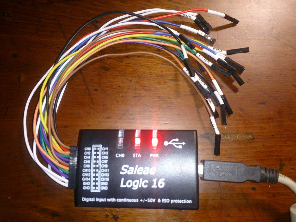
  • Saleae 邏輯分析儀 (一千新台幣有找)

    • 需要自行到Saleae官方網站下載安裝Linux版軟體
  • USB 轉 RS232 TTL 轉接線

測試環境

1
2
3
4
5
6
7
8
9
10
$ lsb_release -a
No LSB modules are available.
Distributor ID:   Ubuntu
Description:  Ubuntu 14.04.4 LTS
Release:  14.04
Codename: trusty

$ arm-none-eabi-gcc --version
arm-none-eabi-gcc (GNU Tools for ARM Embedded Processors) 5.4.1 20160609 (release) [ARM/embedded-5-branch revision 237715]
...

  • SPL版本: STM32F4xx_DSP_StdPeriph_Lib_V1.6.1
  • 開發板: STM32F4 Dicovery, STM32F429-Disco

USART 控制

對於組裝工來說,我想要理解的不是電位差之這些電器信號。甚至在組裝時我也不在意暫存器設定等東西和背後的原理(好孩子不要學)。我關心的是

  1. 我們要用哪些資源?
  2. 這些資源對應的實體腳位是?
  3. 軟體中怎麼樣設定和啟動設備?
  4. 軟體中怎麼樣傳輸資料?

我們針對這四個問題一一處理

我們要用哪些資源?

從手冊可以看到有八個USART可以用。我原本是挑USART1來用,不過後來卡關經過網友提醒發現要避開USART1。後來發現APB2上面除了USART1外另外一個USART是USART6。懶得太多程式碼的情況下就挑了USART6。

這些資源對應的實體腳位是?

一樣要翻手冊。

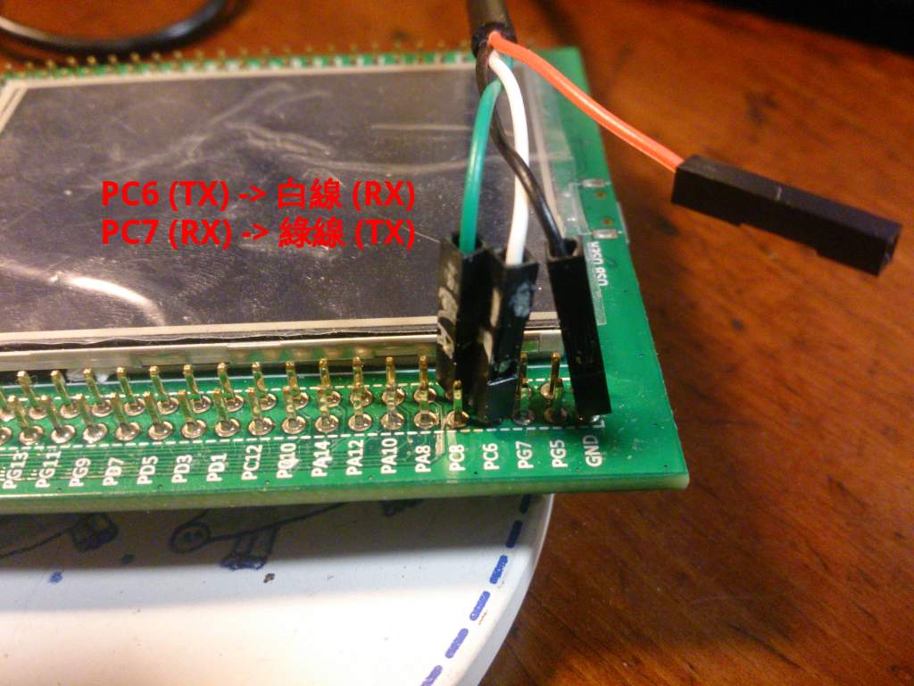
  • PC6: UASRT6 TX
  • PC7: USART6 RX

軟體中怎麼樣設定和啟動設備?

要分兩個部份討論

a. GPIOC 設定

要設定

  • 開啟GPIOC的clock
  • 設定Pin腳,設定PC6和PC7這兩個腳位。為什麼是這兩個腳位請查手冊
    • PC6: 設成Alternate function,也就是USART6 TX
    • PC7: 設成Alternate function,也就是USART6 RX
    • 其他
      • 設定為Pull UP,這和USART通訊協定有關,在IDLE時維持高電位
      • 設定Push-Pull輸出模式,這個我完全不懂只是閉著眼睛抄的

來看大家最討厭看的程式碼片斷吧

1
2
3
4
5
6
7
8
9
10
11
12
13
14
15
16
17
18
19
20
GPIO_InitTypeDef GPIO_InitStructure;

/* Enable GPIOC clock */
RCC_AHB1PeriphClockCmd(RCC_AHB1Periph_GPIOC, ENABLE);

/* Connect USART6_Tx instead of PC6 */
GPIO_PinAFConfig(GPIOC, GPIO_PinSource6, GPIO_AF_USART6);

/* Connect USART6_Rx instead of PC7 */
GPIO_PinAFConfig(GPIOC, GPIO_PinSource7, GPIO_AF_USART6);

/* Configure USART Tx (PC6) and Rx (PC7) as alternate function  */
GPIO_InitStructure.GPIO_Mode  = GPIO_Mode_AF;
GPIO_InitStructure.GPIO_Pin   = GPIO_Pin_6 | GPIO_Pin_7;
GPIO_InitStructure.GPIO_Speed = GPIO_Speed_100MHz;

GPIO_InitStructure.GPIO_OType = GPIO_OType_PP;
GPIO_InitStructure.GPIO_PuPd  = GPIO_PuPd_UP;

GPIO_Init(GPIOC, &GPIO_InitStructure);

b. USART6 設定

依下列步驟

  1. 開啟USART6的clock
  2. 設定USART6
    • 115200 BPS
    • No parity bit
    • 8-bit 資料
    • 1 Stop bit
    • 關閉硬體流量控制
    • TX/RX模式都打開
  3. 啟動UASRT6

一樣來看大家最討厭看的程式碼片斷吧

1
2
3
4
5
6
7
8
9
10
11
12
13
14
15
16
17
18
USART_InitTypeDef USART_InitStruct;

/* Enable USART6 clock */
RCC_APB2PeriphClockCmd(RCC_APB2Periph_USART6, ENABLE);

/* 115200, N81  */
USART_InitStruct.USART_BaudRate = 115200;
USART_InitStruct.USART_WordLength = USART_WordLength_8b;
USART_InitStruct.USART_StopBits = USART_StopBits_1;
USART_InitStruct.USART_Parity = USART_Parity_No;
USART_InitStruct.USART_HardwareFlowControl = USART_HardwareFlowControl_None;
USART_InitStruct.USART_Mode = USART_Mode_Rx | USART_Mode_Tx;

/* Apply USART settings */
USART_Init(USART6, &USART_InitStruct);

/* Enable USART */
USART_Cmd(USART6, ENABLE);

軟體中怎麼樣傳輸資料?

這部份還蠻直覺的,就是檢查狀態。可以送的時候就寫資料到暫存器去;有資料時從暫存器讀出資料。程式碼夠短應該不會那麼討厭吧?另外SPL也有提供USART傳輸接收的函數,請自行查詢。

1
2
3
4
5
6
7
8
9
10
11
12
13
char getchar(void)
{
    while(USART_GetFlagStatus(USART6, USART_FLAG_RXNE) == RESET);
    return USART6->DR & 0xff;
}

void putchar(char c)
{
    /* Wait until data was tranferred */
    while(USART_GetFlagStatus(USART6, USART_FLAG_TXE) == RESET);

    USART6->DR = (c & 0xff);
}

程式碼

最完整可編譯程式碼放在這邊

前面有提到HSE設定需要更動為8MHz。我是在stm32f4xx_conf.h加入以下片斷。

1
2
3
4
5
#if defined  (HSE_VALUE)
/* Redefine the HSE value; it's equal to 8 MHz on the STM32F4-DISCOVERY Kit */
 #undef HSE_VALUE
 #define HSE_VALUE    ((uint32_t)8000000) 
#endif /* HSE_VALUE */

完整程式碼

就是把前面的設定合體再加上一些helper就是了。這個程式也不難,就是印出你打的字。當你按enter後會自動塞入\r並且印出提示符號。

usart.c
1
2
3
4
5
6
7
8
9
10
11
12
13
14
15
16
17
18
19
20
21
22
23
24
25
26
27
28
29
30
31
32
33
34
35
36
37
38
39
40
41
42
43
44
45
46
47
48
49
50
51
52
53
54
55
56
57
58
59
60
61
62
63
64
65
66
67
68
69
70
71
72
73
74
75
76
77
78
79
80
81
82
83
84
85
86
87
88
89
90
91
92
93
94
95
96
97
98
99
100
101
102
103
104
105
106
107
108
#include "stm32f4xx_conf.h"
#include <stm32f4xx.h>
#include <stm32f4xx_gpio.h>
#include <stm32f4xx_usart.h>

void setupUSART(void);

/* helper functions */
void print(char *str);
char getchar(void);
void putchar(char c);

int main(int argc, char **argv)
{
    /* Setup USART */
    setupUSART();

    /* Greeting */
    print("Hello World\n");
    print("\r> ");
    while(1) {
        /* Echo a character */
        char c = getchar();
        putchar(c);

        /* Show prompt with enter */
        if (c == '\n') {
            print("\r> ");
        }
    }

    return 0;
}

void setupUSART(void)
{
    GPIO_InitTypeDef GPIO_InitStructure;

    /* Enable GPIOC clock */
    RCC_AHB1PeriphClockCmd(RCC_AHB1Periph_GPIOC, ENABLE);

    /* Connect USART6_Tx instead of PC6 */
    GPIO_PinAFConfig(GPIOC, GPIO_PinSource6, GPIO_AF_USART6);

    /* Connect USART6_Rx instead of PC7 */
    GPIO_PinAFConfig(GPIOC, GPIO_PinSource7, GPIO_AF_USART6);

    /* Configure USART Tx (PC6) and Rx (PC7) as alternate function  */
    GPIO_InitStructure.GPIO_Mode  = GPIO_Mode_AF;
    GPIO_InitStructure.GPIO_Pin   = GPIO_Pin_6 | GPIO_Pin_7;
    GPIO_InitStructure.GPIO_Speed = GPIO_Speed_100MHz;

    GPIO_InitStructure.GPIO_OType = GPIO_OType_PP;
    GPIO_InitStructure.GPIO_PuPd  = GPIO_PuPd_UP;

    GPIO_Init(GPIOC, &GPIO_InitStructure);

    /********************************************
     * USART set started here
     ********************************************/
    USART_InitTypeDef USART_InitStruct;

    /* Enable USART6 clock */
    RCC_APB2PeriphClockCmd(RCC_APB2Periph_USART6, ENABLE);

    /* 115200, N81  */
    USART_InitStruct.USART_BaudRate = 115200;
    USART_InitStruct.USART_WordLength = USART_WordLength_8b;
    USART_InitStruct.USART_StopBits = USART_StopBits_1;
    USART_InitStruct.USART_Parity = USART_Parity_No;
    USART_InitStruct.USART_HardwareFlowControl = USART_HardwareFlowControl_None;
    USART_InitStruct.USART_Mode = USART_Mode_Rx | USART_Mode_Tx;

    /* Apply USART settings */
    USART_Init(USART6, &USART_InitStruct);

    /* Enable USART */
    USART_Cmd(USART6, ENABLE);
}

char getchar(void)
{
    while(USART_GetFlagStatus(USART6, USART_FLAG_RXNE) == RESET);
    return USART6->DR & 0xff;
}

void putchar(char c)
{
    /* Wait until data was tranferred */
    while(USART_GetFlagStatus(USART6, USART_FLAG_TXE) == RESET);

    USART6->DR = (c & 0xff);
}

void print(char *str)
{
    assert_param(str != 0);
    while(*str) {
        putchar(*str);
        str++;
    }
}

/* Trap here for gdb if asserted */
void assert_failed(uint8_t* file, uint32_t line)
{
    while(1);
}

Makefile

有兩點要說明

  1. 加入stm32f4xx_usart.c
  2. 加入make flash自動燒錄
    • 目前發現使用st-flash燒錄有時候顯示燒錄完成,但是實際上測試還是燒錄前的行為,換成openocd測試中
1
2
3
4
5
6
7
8
9
10
11
12
13
14
15
16
17
18
19
20
21
22
23
24
25
26
27
28
29
30
31
32
33
34
35
36
37
38
39
40
41
42
43
44
45
46
47
48
49
50
51
#----------------------------------------------------------------------------------
# Commom settings
#----------------------------------------------------------------------------------
TARGET=usart
PRJ_ROOT=$(shell cd ../../ ; pwd)
include $(PRJ_ROOT)/conf/build.def

#----------------------------------------------------------------------------------
# Files to build
#----------------------------------------------------------------------------------
SRCS  = $(CMSIS_STARTUP_SRC) $(CMSIS_SYSTEM_SRC)
SRCS += $(STM_DIR)/src/stm32f4xx_gpio.c
SRCS += $(STM_DIR)/src/stm32f4xx_rcc.c
SRCS += $(STM_DIR)/src/stm32f4xx_usart.c
SRCS += usart.c

C_OBJS = $(patsubst %.c, %.o, $(SRCS))   # translate *.c to *.o
OBJS   = $(patsubst %.s, %.o, $(C_OBJS)) # also *.s to *.o files

OUT_OBJS = $(addprefix $(OUT_DIR)/, $(OBJS))

#----------------------------------------------------------------------------------
# Build here
#----------------------------------------------------------------------------------
$(OUT_DIR)/$(TARGET).bin: $(OUT_OBJS)
  $(TOOL_CHAIN_PREFIX)-gcc -Wl,-Map=$(OUT_DIR)/$(TARGET).map,-T$(TARGET).ld -nostartfiles \
      $(CFLAGS) $(OUT_OBJS) -o $(OUT_DIR)/$(TARGET).elf
  $(TOOL_CHAIN_PREFIX)-objcopy -Obinary $(OUT_DIR)/$(TARGET).elf $@
  $(TOOL_CHAIN_PREFIX)-objdump -S $(OUT_DIR)/$(TARGET).elf > $(OUT_DIR)/$(TARGET).list

$(OUT_DIR)/%.o: %.s
  mkdir -p $(dir $@)
  $(TOOL_CHAIN_PREFIX)-gcc -c $(CFLAGS) $< -o $@

$(OUT_DIR)/%.o: %.c
  mkdir -p $(dir $@)
  $(TOOL_CHAIN_PREFIX)-gcc -c $(CFLAGS) $< -o $@

flash: $(OUT_DIR)/$(TARGET).bin
  openocd -f interface/stlink-v2.cfg  \
            -f target/stm32f4x.cfg      \
            -c "init"                   \
            -c "reset init"             \
            -c "stm32f2x unlock 0"      \
            -c "flash probe 0"          \
            -c "flash info 0"           \
            -c "flash write_image erase $< 0x8000000" \
            -c "reset run" -c shutdown

clean:
  rm -fr $(OUT_DIR) gdb.txt

功能驗證

邏輯分析儀驗證

現在邏輯分析儀已經可以自動幫你抓波形分析了。當你下載並解壓縮檔案後,記得更新udev的Rule讓電腦可以認得邏輯分析儀。

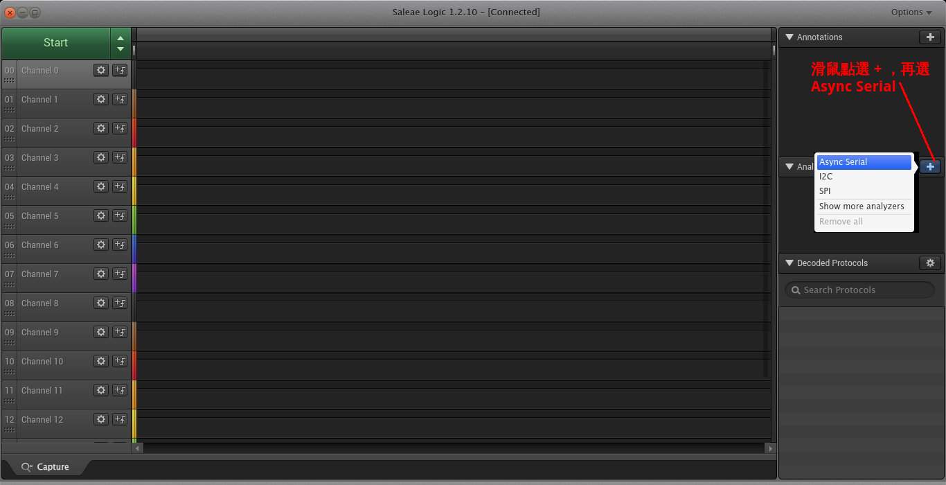
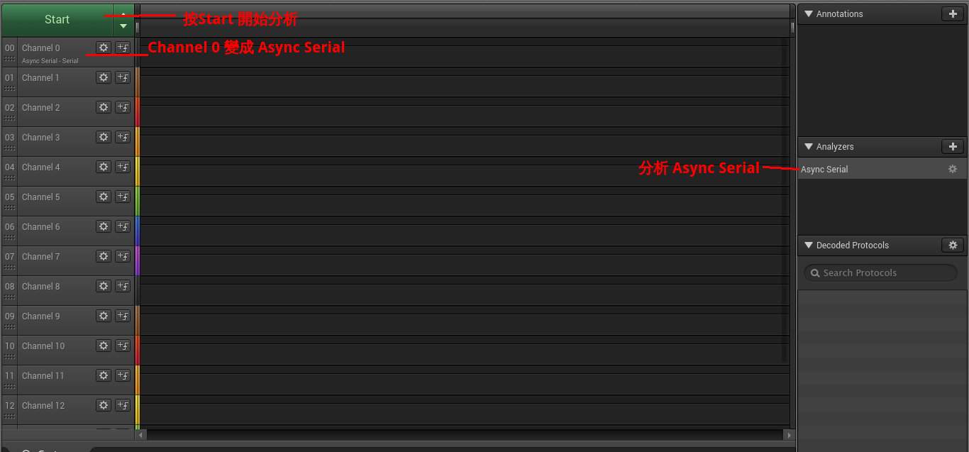
接下來你要設定邏輯分析儀的分析通訊協定為Async Serial 如下圖

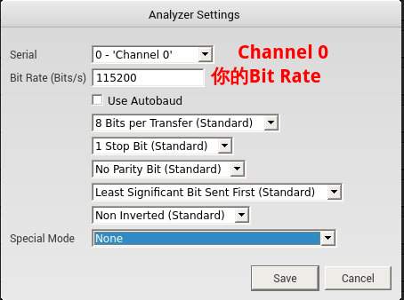
選了Async Serial會有選單出現,你需要設定用第幾個Channel以及USART通訊參數如下圖

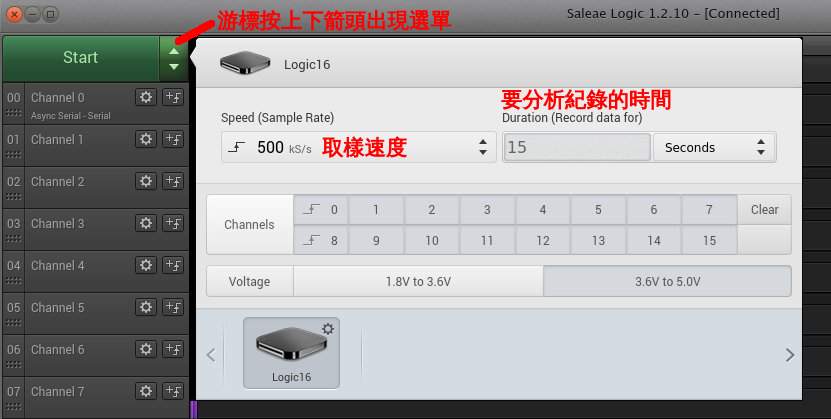
如果需要的話,你可以進一步設定取樣速度、取樣時間如下圖

假設你的邏輯分析儀接腳都接好了就可以按開始分析訊號了

這是一個成功的Hello World波形分析,圖可能有點小,全圖在這邊

實際驗證

你需要先把USB 轉 RS232 TTL 轉接線接到版子上如下圖

我是使用mintern,執行畫面如下

1
2
3
4
5
6
7
8
9
$ miniterm.py -b 115200 -p /dev/ttyUSB0
--- Miniterm on /dev/ttyUSB0: 115200,8,N,1 ---
--- Quit: Ctrl+]  |  Menu: Ctrl+T | Help: Ctrl+T followed by Ctrl+H ---
test
> test
> test
> test
> testast
> teadsatdsasd

參考資料

Auto Photo Watermarking Script

| Comments

因故需要對大量圖片調整解析度並加入浮水印,查了網路找到非常好的範例文章。這篇文章裏面也有script,和我的不太一樣,有興趣的人可以去參考。

更改後寫成script如下,它做了:

  1. 開了processed_pictures目錄,把改過的檔案存到該目錄
  2. 將新的圖案解析度寬度轉成1024
  3. 將產生的圖片quality設成80%
  4. 加入浮水印字串
1
2
3
4
5
6
7
8
9
10
#!/bin/sh
TARGET_DIR=processed_pictures
NEW_WIDTH=1024
CAP="Wen Liao"

mkdir -p $TARGET_DIR
for i in $(ls) ; do
    echo convert $i to $TARGET_DIR
    convert -background '#0008' -quality 80 -resize $NEW_WIDTH -fill white -gravity center -size $(identify -format %w $i)x120 caption:"$CAP" $i +swap -gravity south -composite $TARGET_DIR/$i
done

要注意

  1. 本script假設目前目錄都是圖檔,所以不判斷檔名是否為.jpg或是.png
  2. 無法處理檔名有空白的檔案
  3. 你需要自行安裝imagemagick
  4. 由於相片landscape 和 portrait的關係,浮水印的位址不一定會和你想的一樣,目前為止我不在意這個問題就是了。附上範例轉出的landscape 和 portrait照片各一張

Landscape

Portrait

參考資料

ARM CM4 Pratice (2): 實驗軟體專案規劃和LED閃滅實驗

| Comments

前言

閉著眼睛學東西最困擾的是資料很多,但是完全不知道怎麼從那邊下手。這次運氣很好終於找到大大推荐的入門教材: Discovering the STM32 Microcontroller作為一個突破點。雖然他上面講的是STM32F1,不過改一下還是可以在開發版上面動,短期內的自學大概會以這本書為主。

本篇文章主要是介紹在GNU/Linux下的STM32F429 開發軟體,這次以LED閃滅為實習題目,以後的實習會基於這次的專案為主。有興趣的朋友請自行到我的Github repository取用。注意是這個專案單純自爽,常常會git push -f變動commit,如果有人fork我再調整。

目錄

測試環境

1
2
3
4
5
6
7
8
9
10
$ lsb_release -a
No LSB modules are available.
Distributor ID:   Ubuntu
Description:  Ubuntu 14.04.4 LTS
Release:  14.04
Codename: trusty

$ arm-none-eabi-gcc --version
arm-none-eabi-gcc (GNU Tools for ARM Embedded Processors) 5.4.1 20160609 (release) [ARM/embedded-5-branch revision 237715]
...

  • SPL版本: STM32F4xx_DSP_StdPeriph_Lib_V1.6.1
  • 開發板: STM32F4 Dicovery, STM32F429-Disco
  • SPL 目錄架構
1
2
3
4
5
6
7
8
9
10
11
12
13
14
15
16
17
18
19
20
21
22
23
$ tree -d -L 4
.
└── STM32F4xx_DSP_StdPeriph_Lib_V1.6.1
    ├── _htmresc
    ├── Libraries
    │   ├── CMSIS
    │   │   ├── Device
    │   │   ├── Documentation
    │   │   ├── DSP_Lib
    │   │   ├── Include
    │   │   ├── Lib
    │   │   └── RTOS
    │   └── STM32F4xx_StdPeriph_Driver
    │       ├── inc
    │       └── src
    ├── Project
    │   ├── STM32F4xx_StdPeriph_Examples
    │   └── STM32F4xx_StdPeriph_Templates
    └── Utilities
        ├── Media
        ├── ST
        ├── STM32_EVAL
        └── Third_Party

專案規劃

Discovering the STM32 Microcontroller這本書後啟發的。想法整理如下:

  • 目的:建立一個練習STM32F4開發版的專案
  • 專案需要的資料
    • STM 函式庫 source code
      • 這部份要去官方網站下載,不會放到github上面
    • Build code 共用的設定如toolchain、路徑、compile flag等
    • 一些template 檔案加入開發如Makefile、linker script、config header file

最後的目錄就是這樣。

1
2
3
4
5
6
7
8
9
10
11
12
13
14
15
16
17
18
$ tree -L 3
.
├── conf
│   ├── build.def
│   ├── Makefile.template
│   ├── stm32f4xx_conf.h
│   └── template-bared.ld
├── labs
│   └── 0_led
│       ├── led.c
│       ├── led.ld
│       ├── Makefile
│       └── stm32f4xx_conf.h
├── libraries
│   ├── readme.txt
│   └── STM32F4xx_DSP_StdPeriph_Lib_V1.6.1
├── LICENSE
└── README.md

請注意SPL可能會因為下載版本不同,變數宣告、常數宣告、和檔案名稱路徑可能不同造成編譯失敗,這時候就當組裝作業自己解決吧。

Makefile撰寫

共用變數

這邊我們需要一個共用的設定,在實習的時候直接include。詳細說明如下,懶得看的可以直接看檔案內容

  • Toolchain設定
1
TOOL_CHAIN_PREFIX=arm-none-eabi
  • 路徑設定
    • 我們需要定位專案的最頂端位址才能設定其他路徑的相對位址
    • 除了您自己的檔案,ST 提供的函式庫和ARM的CMSIS在開發都會用到
1
2
3
4
5
PRJ_ROOT?=..
LIB_DIR=$(PRJ_ROOT)/libraries/STM32F4xx_DSP_StdPeriph_Lib_V1.6.1/Libraries
STM_DIR=$(LIB_DIR)/STM32F4xx_StdPeriph_Driver
CMSIS_DIR=$(LIB_DIR)/CMSIS
LDSCRIPT?=$(PRJ_ROOT)/conf/bared.ld
  • 指定開發平台
1
PLATFORM = STM32F429_439xx
  • 設定header file路徑
1
2
3
SPL_INC=$(STM_DIR)/inc
CMSIS_COMMON_INC = $(CMSIS_DIR)/Include
CMSIS_STM32_INC  = $(CMSIS_DIR)/Device/ST/STM32F4xx/Include
  • 指令所有產生的檔案都放到build目錄
1
OUT_DIR=$(PRJ_ROOT)/build
  • 設定start up檔案和system檔案路徑

除非你要自己從flash搬資料到RAM、設定ISR vector、RCC等,不然一定會用到start up 檔案和system檔案。start up 檔案在SPL中有很多範本,我們使用了gcc_ride7這個版本,原因是其他的都沒有gcc這個字眼。

1
2
CMSIS_STARTUP_SRC = $(CMSIS_DIR)/Device/ST/STM32F4xx/Source/Templates/gcc_ride7/startup_stm32f429_439xx.s
CMSIS_SYSTEM_SRC  = $(CMSIS_DIR)/Device/ST/STM32F4xx/Source/Templates/system_stm32f4xx.c
  • 設定debug mode

SPL提供assertion,使用USE_FULL_ASSERT打開。打開以後需要自行實作函數void assert_failed(uint8_t* file, uint32_t line)

1
2
3
4
5
BUILD_MODE = DEBUG

ifeq ($(BUILD_MODE), DEBUG)
        CFLAGS += -DUSE_FULL_ASSERT -g3
endif
  • CPU相關compile flags

STM32F4使用Cotex M4。題外話,對於toolchain有興趣的可以用arm-none-eabi-gcc -Q --help=target查詢有支援哪些平台。

1
ARCH_FLAGS = -mthumb -mcpu=cortex-m4
  • Compile flag分為
    • 增加嚴格的錯誤檢查
    • 設定include 路徑
    • 叫toolchain不要用使用內建的函式庫如libc
1
2
3
4
5
6
7
LDFLAGS += -T$(LDSCRIPT) $(ARCH_FLAGS)

CFLAGS += $(ARCH_FLAGS)
CFLAGS += -I. -I$(SPL_INC) -I$(CMSIS_COMMON_INC) -I$(CMSIS_STM32_INC)
CFLAGS += -D$(PLATFORM) -DUSE_STDPERIPH_DRIVER $(FULLASSERT)
CFLAGS += -Wall -Werror -MMD -std=c99
CFLAGS += -fno-common -ffreestanding -O0

專案Makefile template

這邊直接把LED閃滅的Makefile拿來當template,詳細說明如下,一樣懶得看的可以去這邊看檔案內容。

  • 產生的binary 檔名、定位專案的最頂端位址、並且載入前面的設定檔。
1
2
3
TARGET=led
PRJ_ROOT=$(shell cd ../../ ; pwd)
include $(PRJ_ROOT)/conf/build.def
  • 指定要編譯的SPL 檔案

除了前面前面提到的start up檔案、system檔、還有你自己的程式碼外,根據你的需求,還會需要SPL的驅動程式。這個專案我們需要GPIORCC (reset clock control)這兩個部份。一個是用來控制LED、另外一個用來計算時間產生以控制閃滅。

1
2
3
4
SRCS  = $(CMSIS_STARTUP_SRC) $(CMSIS_SYSTEM_SRC)
SRCS += $(STM_DIR)/src/stm32f4xx_gpio.c
SRCS += $(STM_DIR)/src/stm32f4xx_rcc.c
SRCS += led.c
  • 檔名轉換

上面的是source檔案,但是我們編譯需要把source檔案轉成object檔案並且存在./build目錄下。

1
2
3
4
C_OBJS = $(patsubst %.c, %.o, $(SRCS))   # translate *.c to *.o
OBJS   = $(patsubst %.s, %.o, $(C_OBJS)) # also *.s to *.o files

OUT_OBJS = $(addprefix $(OUT_DIR)/, $(OBJS))
  • 產生led.bin

不要被符號嚇到,說明如下

* 產生build/led.bin檔,前提是上面的object 檔案都編譯完成
* 產生方式
    * 叫gcc 從前面的object檔案中,透過led.ld linker script產生出build/led.elf、build/led.map (debug用)
    * 從build/led.elf產生build/led.bin
    * 從build/led.elf產生build/led.list (debug用)
1
2
3
4
5
$(OUT_DIR)/$(TARGET).bin: $(OUT_OBJS)
  $(TOOL_CHAIN_PREFIX)-gcc -Wl,-Map=$(OUT_DIR)/$(TARGET).map,-T$(TARGET).ld -nostartfiles \
      $(CFLAGS) $(OUT_OBJS) -o $(OUT_DIR)/$(TARGET).elf
  $(TOOL_CHAIN_PREFIX)-objcopy -Obinary $(OUT_DIR)/$(TARGET).elf $@
  $(TOOL_CHAIN_PREFIX)-objdump -S $(OUT_DIR)/$(TARGET).elf > $(OUT_DIR)/$(TARGET).list
  • 編譯並產生object 檔案
1
2
3
4
5
6
7
$(OUT_DIR)/%.o: %.s
  @mkdir -p $(dir $@)
  $(TOOL_CHAIN_PREFIX)-gcc -c $(CFLAGS) $< -o $@

$(OUT_DIR)/%.o: %.c
  @mkdir -p $(dir $@)
  $(TOOL_CHAIN_PREFIX)-gcc -c $(CFLAGS) $< -o $@
  • 燒錄

可以下make flash燒錄。使用openocd的原因是因為st-flash偶爾會有寫燒錄完成但是實際上沒有燒進去的情況

1
2
3
4
5
6
7
8
9
10
flash: $(OUT_DIR)/$(TARGET).bin
  openocd -f interface/stlink-v2.cfg  \
            -f target/stm32f4x.cfg      \
            -c "init"                   \
            -c "reset init"             \
            -c "stm32f2x unlock 0"      \
            -c "flash probe 0"          \
            -c "flash info 0"           \
            -c "flash write_image erase $< 0x8000000" \
            -c "reset run" -c shutdown
  • 以下不解釋
1
2
clean:
  rm -fr $(OUT_DIR) gdb.txt

第一支程式: LED閃滅

Linker script 和 start up檔案

Linker script

linker script (全文),這個script是從成大課程作業修改的,簡單解釋如下

  • 有兩塊記憶體,一個是FLASH一個是RAM,FLASH 不可寫入。
  • 那些.text.data.bss就不解釋了。我們這次關注下列的symbols
    • _sidata
    • _sdata
    • _edata
    • _sbss
    • _ebss
    • _estack

Start up檔案

上面的這些symbol,可以對照這邊的start up 程式碼中的reset_handler,可以發現:

搞定.bss.data後,接下來start up會去呼叫systemInit,而systemInit就在system_stm32f4xx.c裏面。設定完系統後就是你寫的程式碼main上場了。

start up 檔案剩下的部份就是.isr_vector,可以想像成一個function pointer陣列(除了最開始的stack pointer,注意stack pointer初始值也是在linker script中設定的)。

另外一個要注意的是start up source code的順序和放在記憶體的順序不一致,真正在記憶體的順序請參考linker script

GPIO API

設定順序如下

  • 開發版手冊找出要控制燈號的GPIO
    • 我程式就是輪流點亮點滅LED 3和LED 4,手冊上說是GPIO G的第13和14腳位
  • 打開GPIO的clock(猜測嵌入式系統的電耗考慮,沒再用的設備都不開clock省電)
  • 設定GPIO腳位的為輸出頻率為2MHz
GPIO設定
1
2
3
4
5
6
7
8
9
10
11
void setupLED(GPIO_InitTypeDef *LED_InitStruct)
{
    /* Setup LED GPIO */
    RCC_AHB1PeriphClockCmd(RCC_AHB1Periph_GPIOG, ENABLE);

    GPIO_StructInit(LED_InitStruct);
    LED_InitStruct->GPIO_Pin   = GPIO_Pin_13 | GPIO_Pin_14 ;
    LED_InitStruct->GPIO_Mode  = GPIO_Mode_OUT;
    LED_InitStruct->GPIO_Speed = GPIO_Speed_2MHz;
    GPIO_Init(GPIOG, LED_InitStruct);
}
  • 輸出資料到GPIO範例如下
輸出資料到GPIO範例
1
GPIO_WriteBit(GPIOG, GPIO_Pin_13 , 1);

Timer ISR

要做的是

  • 設定timer interrupt 出現的週期,設定成nano second的程式碼如下
1
2
3
4
/* Setup timer interrupt interval to nano second */
if(SysTick_Config(SystemCoreClock / 1000)) {
    while(1); /* Trap here if failed */
}
  • time out的ISR,基本上就是計數counter加上busy waiting而已
1
2
3
4
5
6
7
8
static __IO uint32_t g_timeToWakeUp;
void sleep(uint32_t nSec)
{
    g_timeToWakeUp = nSec;

    /* Busy waiting */
    while(g_timeToWakeUp != 0);
}

程式碼

這邊的assertion 實作單純是一個無限迴圈,當assertion失敗就會陷入這個迴圈。這時候用除錯器就可以找到出現assertion的行號了。

寫了以後開始修改程式碼或Makefile直到編譯過以後才針對程式行為除錯。

led.c
1
2
3
4
5
6
7
8
9
10
11
12
13
14
15
16
17
18
19
20
21
22
23
24
25
26
27
28
29
30
31
32
33
34
35
36
37
38
39
40
41
42
43
44
45
46
47
48
49
50
51
52
53
54
55
56
57
58
59
60
61
62
63
64
65
66
67
68
69
70
#include "stm32f4xx_conf.h"
#include <stm32f4xx.h>
#include <stm32f4xx_gpio.h>

/* A Led blink lab for STM32 Discovry Disco                   *
 * Based on:                                                  *
 *   Discovering the STM32 Microcontroller by Geoffrey Brown. */

void setupLED(GPIO_InitTypeDef *LED_InitStruct);
void sleep(uint32_t nSec);

int main(int argc, char **argv)
{
    static int LEDVal = 0;
    GPIO_InitTypeDef LED_InitStruct;

    /* Setup LED */
    setupLED(&LED_InitStruct);

    /* Setup timer interrupt interval to nano second */
    if(SysTick_Config(SystemCoreClock / 1000)) {
        while(1); /* Trap here if failed */
    }

    /* Blinking LED3 and LED4 */
    while(1) {
        GPIO_WriteBit(GPIOG, GPIO_Pin_13 , LEDVal);
        GPIO_WriteBit(GPIOG, GPIO_Pin_14 , !LEDVal);

        sleep(250);
        LEDVal = !LEDVal;
    }

    return 0;
}

void setupLED(GPIO_InitTypeDef *LED_InitStruct)
{
    /* Setup LED GPIO */
    RCC_AHB1PeriphClockCmd(RCC_AHB1Periph_GPIOG, ENABLE);

    GPIO_StructInit(LED_InitStruct);
    LED_InitStruct->GPIO_Pin   = GPIO_Pin_13 | GPIO_Pin_14 ;
    LED_InitStruct->GPIO_Mode  = GPIO_Mode_OUT;
    LED_InitStruct->GPIO_Speed = GPIO_Speed_2MHz;
    GPIO_Init(GPIOG, LED_InitStruct);
}

static __IO uint32_t g_timeToWakeUp;
void sleep(uint32_t nSec)
{
    g_timeToWakeUp = nSec;

    /* Busy waiting */
    while(g_timeToWakeUp != 0);
}

/* ISR for system tick */
void SysTick_Handler(void)
{
    if (g_timeToWakeUp != 0x00) {
        g_timeToWakeUp--;
    }
}

/* Trap here for gdb if asserted */
void assert_failed(uint8_t* file, uint32_t line)
{
    while(1);
}

比較有趣的是int LEDVal = 0;一定要宣告成static,否則LED完全沒反應。在網路上請教似乎和進出ISR的時候context備份有關係,這部份有空再找時間了解一下,這次先跳過。

  • 更新,後來測試不管是沒有static,把static改成volatile,都出現第一次燒錄行為不正常,多燒幾次又正常的情況。需要再重新釐清。

燒錄和測試

  • 直接在工作目錄下執行make
1
2
3
4
5
STM32F429-Discovery-Disco-Pratice/labs/0_led$ make
arm-none-eabi-gcc -c -DUSE_FULL_ASSERT -g3 -mthumb -mcpu=cortex-m4 -I. -I../../libraries/STM32F4xx_DSP_StdPeriph_Lib_V1.6.1/Libraries/STM32F4xx_StdPeriph_Driver/inc -I../../libraries/
...
arm-none-eabi-objcopy -Obinary ../../build/led.elf ../../build/led.bin
arm-none-eabi-objdump -S ../../build/led.elf > ../../build/led.list
  • 燒錄指令如下
1
2
3
4
5
6
7
8
STM32F429-Discovery-Disco-Pratice/labs/0_led$ st-flash write ../../build/led.bin  0x8000000
2016-07-25T11:31:28 INFO src/stlink-common.c: Loading device parameters....
2016-07-25T11:31:28 INFO src/stlink-common.c: Device connected is: F42x and F43x device, id 0x10036419
...
enabling 32-bit flash writes
size: 11596
2016-07-25T11:31:28 INFO src/stlink-common.c: Starting verification of write complete
2016-07-25T11:31:29 INFO src/stlink-common.c: Flash written and verified! jolly good!

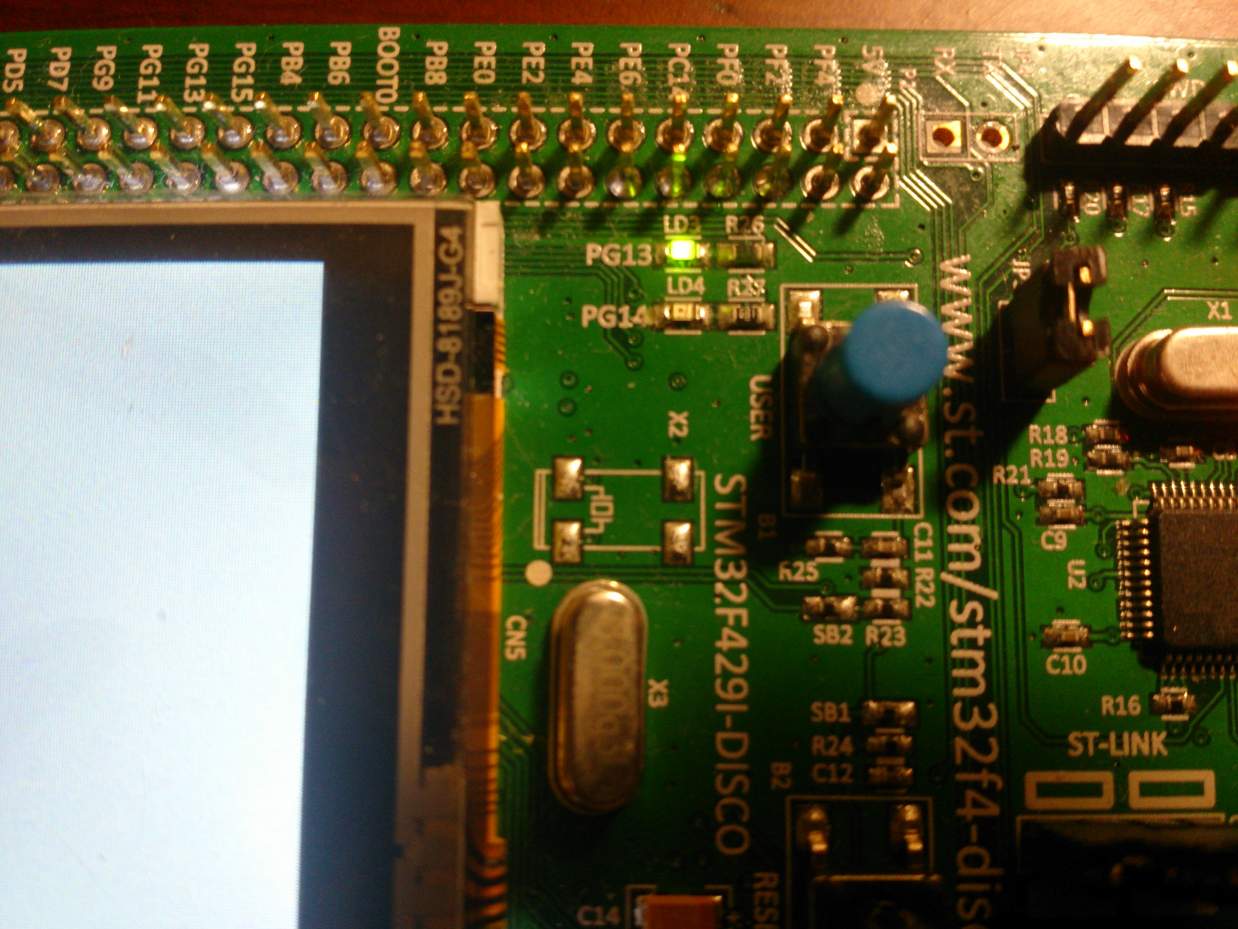
以下是LED點亮結果

參考資料

ARM CM4 Pratice (1): STM32 F4xx Standard Peripherals Library手冊整理

| Comments

前言

以前在寫作業的時候,從來沒有想過那些週邊到底怎麼使用,只大概印象和CMSIS有關。後來想應該是要去了解到底這些廠商提供的函式庫在軟體開發中扮演了什麼樣的角色?因此花了時間整理如下。

在使用之前,請自行到官方網站下載STM32F4 DSP and standard peripherals library。

目錄

簡介

手冊上提到Standard Peripherals Library (以下簡稱SPL)的特點

  • 提供STM32F4 XX的週邊驅動程式和常用的資料結構
  • 基於CMSIS開發
  • ANSI C開發
  • 使用SPL表示週邊設備存取效能和佔用的記憶體空間是由SPL決定,因此有特別限制的話必須要自行最佳化或是實作

SPL包含:

  • 週邊設備暫存器的位址mapping,包含這些暫存器的bit
  • 所有週邊的控制function以及對應的資料結構
  • 範例程式

CMSIS和Standard Peripherals Library說明

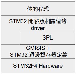
整體的架構圖如下(參考手冊資料)

簡單說明如下

  • CMSIS 提供了
    • 統一的暫存器定義、位址定義
    • 協助開發的函數
    • RTOS 介面
    • DSP 相關函數
  • 開發版上實體的週邊驅動程式是透過SPL和CMSIS來控制硬體

Coding rules and conventions

一般命名規則

  • 函數名稱以大寫週邊簡寫為prefix如USART_SendData
  • 文件舉例的API,請自行望文生義
    • 週邊名稱_Init
    • 週邊名稱_DeInit
    • 週邊名稱_StructInit
    • 週邊名稱_Cmd
    • 週邊名稱_ITConfig
      • IT: interrupt
    • 週邊名稱_DMAConfig
    • 週邊名稱_XXXConfig
      • 週邊設備的XXX設定
    • 週邊名稱_GetFlagStatus
    • 週邊名稱_ClearFlag
    • 週邊名稱_ClearITPendingBit

週邊 Register 命名規則

  • 週邊 Register 一律包裝在struct中,名稱一律為大寫。在 stm32f4xx.h 另外已經宣告了週邊設備位址的結構如:
1
#define SPI1                  ((SPI_TypeDef *) SPI1_BASE)

SPI_TypeDef為一個struct,因此你可以使用下面方式直接存取週邊設備暫存器。

1
SPI1->CR1 = 0x0001;

有了大概概念後,接下來就是開幹時間,敬請期待。

參考資料

使用strace找出程式缺少的檔案路徑

| Comments

這算極短篇。在組裝別人軟體的時候,常常出現缺少檔案的錯誤,運氣不好的不會跟你說缺少的檔案的期待路徑;運氣更差的就會連錯誤都不印,直接程式crash。我後來知道strace之後,才發覺它可以結省很多印log和trace程式碼的時間。

這次就以前一篇執行openocd遇到的問題為例:第一次編譯openocd後,直接執行會出現找不到openocd.cfg檔案。經過一些試誤後才有上一篇整理出來的指令。

錯誤訊息如下

1
2
3
4
5
6
7
8
9
10
11
12
$ openocd 
Open On-Chip Debugger 0.10.0-dev-00250-g9c37747 (2016-04-07-22:20)
Licensed under GNU GPL v2
For bug reports, read
  http://openocd.org/doc/doxygen/bugs.html
embedded:startup.tcl:60: Error: Can't find openocd.cfg
in procedure 'script' 
at file "embedded:startup.tcl", line 60
Error: Debug Adapter has to be specified, see "interface" command
embedded:startup.tcl:60: Error: 
in procedure 'script' 
at file "embedded:startup.tcl", line 60

用strace 觀察輸出訊息如下:

1
2
3
4
5
6
$ strace -f openocd 2>&1  | grep cfg
open("openocd.cfg", O_RDONLY)           = -1 ENOENT (No such file or directory)
open("/home/asdf/.openocd/openocd.cfg", O_RDONLY) = -1 ENOENT (No such file or directory)
open("/usr/local/share/openocd/site/openocd.cfg", O_RDONLY) = -1 ENOENT (No such file or directory)
open("/usr/local/share/openocd/scripts/openocd.cfg", O_RDONLY) = -1 ENOENT (No such file or directory)
write(2, "embedded:startup.tcl:60: Error: "..., 118embedded:startup.tcl:60: Error: Can't find openocd.cfg

從輸出訊息可以知道,openocd會依下面的順序讀取openocd.cfg

  • 目前目錄的openocd.cfg
  • ~/.openocd/openocd.cfg
  • /usr/local/share/openocd/site/openocd.cfg
  • /usr/local/share/openocd/scripts/openocd.cfg

所以接下來就是在openocd的原始碼中挑和你開發target可以使用config 檔案,放入~/.openocd、改成openocd.cfg。當然事情沒那麼簡單,解掉這個問題接下來還會有一些缺少檔案的問題,一樣靠strace就可以搞定。

ARM CM4 Pratice (0): Environment Setup

| Comments

很久以前買了STM32F4 Disco的開發版繁體中文資訊),最近開始想要學習ARM架構和硬體控制等技術。在設定目標,規劃進度前,一定要先把編譯和燒錄環境架設起來,整理如下:

目錄

安裝作業系統環境

1
2
3
4
5
6
$ lsb_release -a
No LSB modules are available.
Distributor ID:   Ubuntu
Description:  Ubuntu 14.04.4 LTS
Release:  14.04
Codename: trusty

安裝步驟

要開發非本機的平台,我們會需要安裝

  • Toolchain:提供編譯,函數,分析binary等功能
  • 燒錄軟體
  • 除錯工具

st-link和openocd同時有燒錄和開發版軟體除錯的功能,因此我們兩個都安裝。

安裝Toolchain

網路上找到GCC ARM Embedded (ARM R和M系列使用 )的PPA。簡單找一下網路,沒有直接證據說這邊的PPA是由ARM官方維護。不過在mbed(ARM 成立的IoT作業系統)網站裏面的確有提到這個PPA,暫時當作間接證據。目前我還沒有驗證這個Toolchain編譯出來的binary是否可以在開發版上正常動作

安裝Toolchain指令
1
2
3
sudo add-apt-repository ppa:team-gcc-arm-embedded/ppa
sudo apt-get update
sudo apt-get install gcc-arm-embedded

手動安裝燒錄和除錯工具

安裝需要套件

系統安裝設定STM32F4環境相關套件
1
2
3
4
5
6
7
8
sudo apt-get install git
sudo apt-get install libtool
sudo apt-get install automake
sudo apt-get install autoconf
sudo apt-get install pkg-config
sudo apt-get install libusb-1.0-0-dev
sudo apt-get install libftdi-dev   # 當openocd要支援MPSSE mode才需要裝,這是啥我不知道。
sudo apt-get install libhidapi-dev # 當openocd要支援CMSIS-DAP才會用到,這是啥我不知道。

我自己的習慣是非必要不會放在系統中,接下來的指令都是預設st-linkopenocd裝到$HOME/bin,Ubuntu在登入時會自動將~/bin加入PATH中。

如果您沒有~/bin的話,請使用下面指令建立。

系統安裝設定STM32F4環境相關套件
1
2
mkdir ~/bin/
. ~/.profile # 強迫系統自動將`~/bin`加入`PATH`中

手動安裝st-link

簡單講一下,就是下載、編譯、安裝軟體。特別要注意的是,為了要讓你的PC在使用Mini USB連到開發版後能夠讓Ubuntu的udev服務可以順利地偵測到開發版,需要加入相關設定並重新啟動udev服務。

下載Source code

下載Source code
1
git clone https://github.com/texane/stlink

編譯stlink

編譯
1
2
3
4
5
cd stlink/
./autogen.sh
./configure
make
cp st-* ~/bin

設定並重新起動udev

設定並重新起動udev
1
2
sudo cp 49-stlinkv* /etc/udev/rules.d/ -rv
sudo service udev restart

驗證一下是否可以偵測到開發版,請確定測試前開發版已經和您的電腦透過Mini USB連線,以及有設定udev並且重新啟動。

1
2
3
4
5
6
7
$ st-probe
Found 1 stlink programmers
30303030303030303030303100
   flash: 2097152 (pagesize: 16384)
    sram: 262144
  chipid: 0x0419
   descr: F42x and F43x device

手動安裝OpenOCD

下載Source code

下載Source code
1
git clone git://git.code.sf.net/p/openocd/code openocd-code

編譯

編譯
1
2
3
4
cd openocd-code/
./bootstrap
./configure # script會自動偵測系統是否有相依開發套件
make

安裝

安裝
1
2
3
cp src/openocd ~/bin
cp tcl/board/stm32f429discovery.cfg ~/.openocd/openocd.cfg
cp tcl/* ~/.openocd

驗證一下是否可以偵測到開發版,請確定測試前開發版已經和您的電腦透過Mini USB連線。

1
2
3
4
5
6
7
8
9
10
11
12
13
14
15
16
17
$ openocd
Open On-Chip Debugger 0.10.0-dev-00250-g9c37747 (2016-04-07-22:20)
Licensed under GNU GPL v2
For bug reports, read
  http://openocd.org/doc/doxygen/bugs.html
Info : The selected transport took over low-level target control. The results might differ compared to plain JTAG/SWD
adapter speed: 2000 kHz
adapter_nsrst_delay: 100
none separate
srst_only separate srst_nogate srst_open_drain connect_deassert_srst
Info : Unable to match requested speed 2000 kHz, using 1800 kHz
Info : clock speed 1800 kHz
Info : STLINK v2 JTAG v17 API v2 SWIM v0 VID 0x0483 PID 0x3748
Info : using stlink api v2
Info : Target voltage: 2.862887
Info : stm32f4x.cpu: hardware has 6 breakpoints, 4 watchpoints

驗證燒錄

事前準備

下載jserv整理的STM 軔體

1
git clone https://github.com/jserv/stm32f429-demos

將source中的hex轉成binary

1
2
cd stm32f429-demos/
make

使用下載提供的Makefile燒錄,裏面會先用openocd燒錄,失敗的話自動切到st-flash燒錄,非常建議讀一下Makefile。

1
make flash-demo檔案

目前套件內蒐集的demo檔案

  • flash-GamesInJava
  • flash-STM32F429I-DISCOVERY_Demo_V1.0.1
  • flash-Paint
  • flash-TouchGFX-demo2014
  • flash-STM32CubeDemo_STM32F429I-Discovery

使用st-flash 開發版燒錄

  • st-flash write 軔體binary檔案名稱 0x8000000

為什麼是0x800000呢?可以查一下手冊,上面有說這塊記憶體是分配給flash memory。

使用openocd 開發版燒錄

GitHub: jserv/stm32f429-demos裏面的Makefile抄來的。指令比較長,不過這是因為openocd可以把一系列的命令連發的關係

1
openocd -f interface/stlink-v2.cfg  -f target/stm32f4x.cfg  -c "init"  -c "reset init"  -c "stm32f2x unlock 0"  -c "flash probe 0"  -c "flash info 0"  -c "flash write_image erase 軔體binary檔案名稱 0x8000000"  -c "reset run" -c shutdown

使用比較好看的排版

1
2
3
4
5
6
7
8
9
openocd -f interface/stlink-v2.cfg  \
        -f target/stm32f4x.cfg      \
        -c "init"                   \
        -c "reset init"             \
        -c "stm32f2x unlock 0"      \
        -c "flash probe 0"          \
        -c "flash info 0"           \
        -c "flash write_image erase 軔體binary檔案名稱 0x8000000" \
        -c "reset run" -c shutdown

參數說明

  • -f
    • 指定config檔案。你可能會想問說interface目錄在那邊,還記得前面的動作嘛?
    • 可以指定
      • interface: 除錯使用的介面
      • target: 執行的平台CPU如STM32F4
      • board: 開發版
  • -c
    • 執行openocd指令

指令說明

  • -f interface/stlink-v2.cfg
  • -f target/stm32f4x.cfg
  • -c "init"
    • 結束config stage,開始進入run stage (出處)
  • -c "reset init"
    • reset 開發版,重新開機(出處)後進入init狀態。
  • -c "stm32f2x unlock 0"
    • 將開發版的flash解鎖(出處)
  • -c "flash probe 0"
    • 偵測開發版的flash(出處)
  • -c "flash info 0"
    • 顯示開發版的flash資訊(出處)
  • -c "flash write_image erase 軔體binary檔案名稱 0x8000000"
    • 將檔案寫入flash(出處)
  • -c "reset run" -c shutdown

參考資料